46
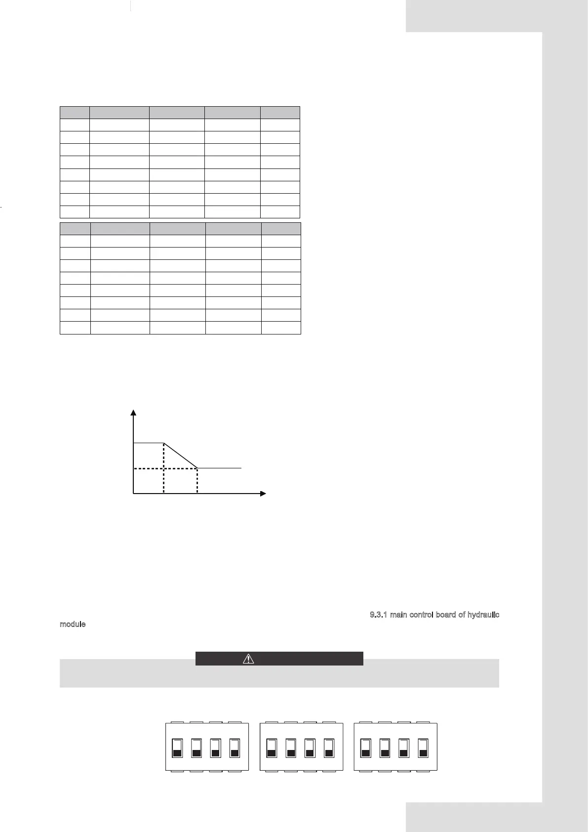
Temperature curves for cooling mode
DIP switch S1,S2 and S4 are located on the main control hydraulic module board (see "9.3.1 main control board of hydraulic
module").
Switch off the power supply before making any changes to the DIP switch settings.
WARNING
10.2.1 Function setting
10.2 DIP switch settings overview
The automatic setting curve is the ninth curve,the ninth curve can be set as following:
State:In the setting the wired controller, if T4C2<T4C1,then exchange their value; if T1SETC1<T1SETC2, then
exchange their value.
1 2 3 4 1 2 3 4
S1 S2
ONOFF
1 2 3 4
S4
T4 - 10≤ T4<15 15≤ T4<22 22≤ T4<30 30≤ T4
1- T1S 16 11 8 5
2- T1S 17 12 9 6
3- T1S 18 13 10 7
4- T1S 19 14 11 8
5- T1S 20 15 12 9
6- T1S 21 16 13 10
7- T1S 22 17 14 11
8- T1S 23 18 15 12
T4 - 10≤ T4<15 15≤ T4<22 22≤ T4<30 30≤ T4
1- T1S 20 18 17 16
2- T1S 21 19 18 17
3- T1S 22 20 19 17
4- T1S 23 21 19 18
5- T1S 24 21 20 18
6- T1S 24 22 20 19
7- T1S 25 22 21 19
8- T1S 25 23 21 20
T4C1
T4C2
T1SETC
2
T1SETC1
T4

 Loading...


