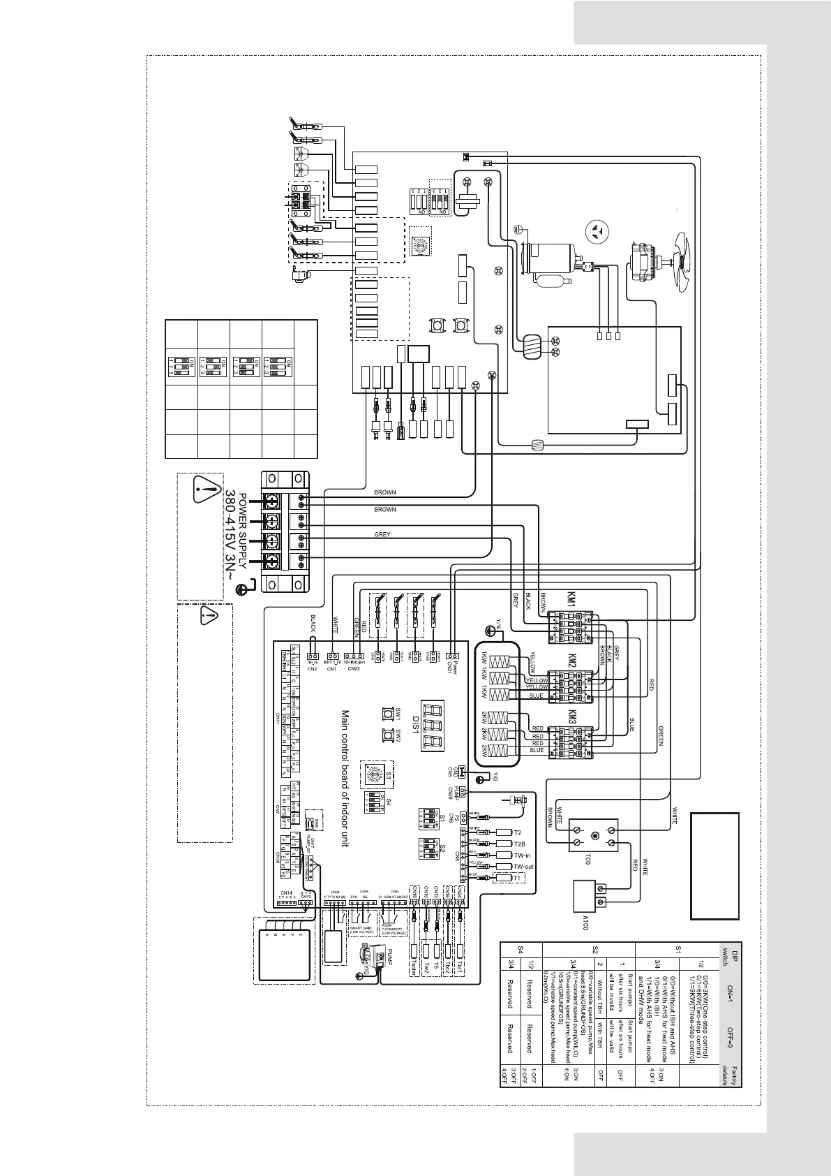
Annex H: Electrically controlled wiring diagram
1-phase 8/10kW +3-phase 9kW backup heater
CN3
L-OUT
CN22
CN24
U
V
CN501 CN502
W
ACL
ACN
12/9V
BLUE
BLUE
FAN
CN28
BROWN
BROWN
CN24
BLACK
BLUE
RED
FORCE_COOL
CHECK
L-OUT
PCB A,Inverter
board for 1phase
PCB B,Main control
board for 1phase
T3
T4
EEV
SV6
STF
BLUE
BLUE
HEAT1-1
BROWN
HEAT1-2
BROWN
P E Q
COMP
SW1SW2
XT2
Y/G
U
V
W
MR3
MR4
CN27
N-OUT
U(R)
V(S)
W(C)
H-PRO
HEAT1-2
HEAT1-1
SV6
STF
HEAT2
HEAT3
HEAT4
EEV1
PE1
Th
MR2
Tp
CN9
CN4
P-SEN
L-PRO
CN1
CN8
CN13
CN14
CN29
CN11
CN10
L-IN
N-IN
T3
T4
Th
Tp
P-SEN
H-PRO
L-PRO
CN18
CN7
CN5
CN6
CN21
CN33
CN16
CN19
HEAT4
CN2
CN30
E H2 H1
E Y X
CN36
CN37
CN38
T2A
T2C
HEAT3
HEAT2
PE2
CN17 CN26
DEBUG
CN20 CN19
CN32
CT1
To the heating
tape of drainage
outlet(<200mA)
4KW
6KW
8KW
0
S6-1
FACTORY
SETTING
S6-2 S6-3
0 0
0
0
0
1
1 0
10KW
1 1 0
S5 S6
S3
IBH
Heat belt
Heat belt
Heat belt
Heat belt
Temperture
Controller
L1 NL3L2
FS
WIRE
CONTROLLER
Leakage Protection Switch
must be installed to the Power
Supply of the electric heating.
Equipment must be grounded.
Operate the switches and push buttons with an
insulated stick (such as a closed ball-point pen)
to avoid touching of live parts.
▪
▪
Querying exteral parameters and setting menu
parameters are only allowed on the wire controller.
BLACK
BLUE
The wiring picture
shown is for reference
only,actual product may
vary.
1:ON
2:ON

 Loading...


