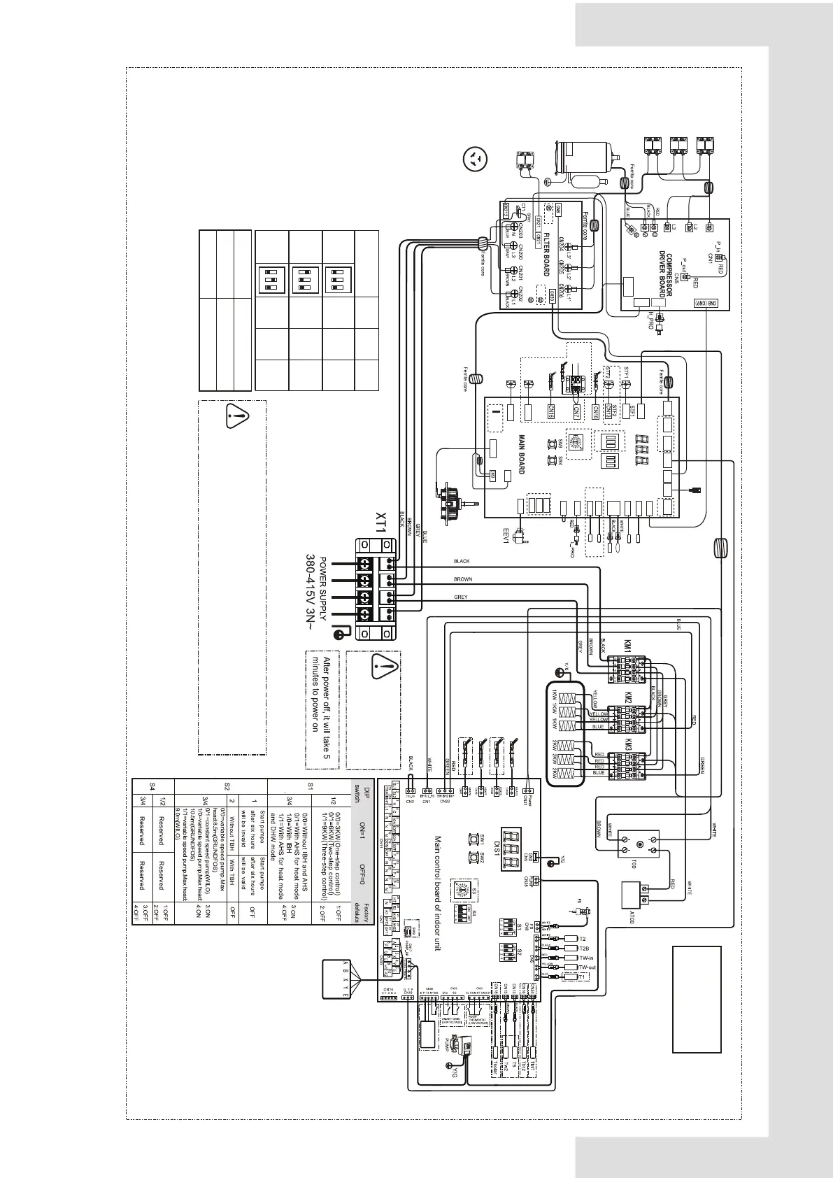
Annex J: Electrically controlled wiring diagram
3-phase 12/14/16kW +3-phase 9kW backup heater
OUTDOOR UNIT POWER SUPPLY
Heat belt
Heat belt
Heat belt
Heat belt
Ferrite Core
IBH
Temperture
Controller
Leakage Protection Switch
must be installed to the Power
Supply of the electric heating.
Equipment must be grounded.
WIRE
CONTROLLER
HEAT SOURCE
L1
RA1
RA2
RA3
BROWN
BLACK
GRAY
BLACK
BROWN
GRAY
FORCE
COOL
CHECK
S3
ADDRESS
HEAT3
HEAT3
SV6
SV6
CN27
SV5
SV5
CN20
TH
TP
CN33
CN34
T2c
T2a
H-SEN
H-SEN
T2c
T2a
CN24
CN38
Earth
CN41
CN18
CN16
CN7
CN15
CN17
CN18
CN19
4
3
RA4
ADDITIONAL
Y/G
CN30
+15V
CN20
CN23
DSP1
S5
1 2 3
ON
S6
1 2 3
ON
CN109
CN2
DC310V
UPFAN
FAN
CN4 CN6
HEAT2
CN26 CN19
CANPOWER PQE
CN32
O-COMP
L-SEN
TH
TP
T4
T3
L_PRO
H_PRO
CN31
CN29
EEV1
CN22
CN35
CN28
CN37
CN36
CN5
CN8
CN9
HEAT1
HEAT1
CN21
POWER-I
BLACK
BROWN
GRAY
BLACK
BROWN
GRAY
RED BLUE
BLACK
U
V
W
PE1
PE2
PE3
RED
HEAT2
XT3
To the heating
tape of
drainage
outlet
(<200mA)
L1 NL3L2
Temp. Sensor code
T3/T4/Th
Tp
Property values
B
25/50
=4100K, R
25℃
=10kΩ
B
25/50
=3950K, R
90℃
=5kΩ
12KW
14KW
0
S6-1
FACTORY
ON
32
1
ON
32
1
SETTING
ON
32
1
ON
32
1
ON
32
1
ON
32
1
S6-2 S6-3
0 0
0
0
1
16KW
1
0
0
Operate the switches and push buttons with an insulated
stick (such as a closed ball-point pen) to avoid touching of
live parts.
▪
▪
Querying exteral parameters and setting menu parameters
are only allowed on the wire controller.
The wiring picture
shown is for reference
only,actual product may
vary.

 Loading...


