Do you have a question about the Midea MV5-X252W/V2GN1 and is the answer not in the manual?
| Brand | Midea |
|---|---|
| Model | MV5-X252W/V2GN1 |
| Category | Air Conditioner |
| Language | English |
Details on indoor and outdoor unit capacities and types.
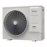
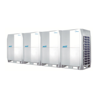
Visuals and descriptions of various indoor and outdoor unit types.
Factory-recommended combinations of outdoor units for different capacities.
Guidelines for indoor and outdoor unit capacity ratio limitations.
Identification and location of key functional components in outdoor units.
Schematic diagrams illustrating refrigerant piping for different unit models.
Visual representation of refrigerant flow during various operating modes.
Overview of the system's control logic and operation sequence.
Reasons and procedures for system stop operations.
Control mechanisms for the system when in standby mode.
Procedures and component control during system startup.
Component control strategies during normal cooling and heating operations.
Systems and measures for protecting the unit from abnormal conditions.
Specific control functions like duty cycling and oil return operations.
General introduction to field settings for outdoor units.
Configuration of DIP switches on the main PCB for unit settings.
Settings for various operating modes via PCB switches.
Configuration of communication addressing modes for outdoor units.
Diagrams showing the layout of components within the electric control box.
Details on the main printed circuit board types, ports, and components.
A comprehensive list of error codes and their content.
Step-by-step procedures for diagnosing and resolving various error codes.
Supplementary information, including temperature sensor resistance characteristics.