English-19
004-1055-00
TP210 Rev. A
© 2013 Midmark Corp. | 60 Vista Drive Versailles, OH 45380 USA | 1-800-643-6275 | 1-937-526-3662 |
[Revised: mo/dd/yr]
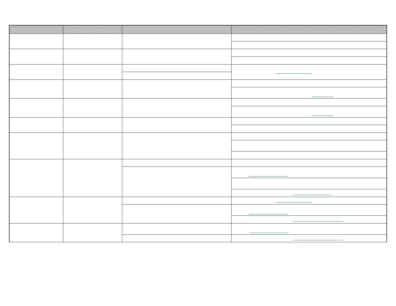
ID Code 02 (Base / Power Supply Board)
Error Code Error Denition Probable Cause Correction
00
Power-Up Fault Board malfunction.
Disconnect power cord for at least ve seconds, then plug back in.
Replace Power Supply PC Board.
01
Power-Up Initialization Fault Board malfunction.
Disconnect power cord for at least ve seconds, then plug back in.
Replace Power Supply PC Board.
02
Calibration Failed / Not Complete
The maximum position was unable to be set.
Calibrate Table. Refer to: Calibration Procedure
A motor control error occurred.
03
Low Voltage 48 VDC Board Malfunction.
Disconnect power cord for at least ve seconds, then plug back in.
If LED’s (D-21 & D-22) are illuminated, replace Power Supply PC Board.
If LED’s (D-21 & D-22) are not illuminated, test Power Toroid
04
Low Voltage 48 VDC Board Malfunction.
Disconnect power cord for at least ve seconds, then plug back in.
If LED’s (D-21 & D-22) are illuminated, replace Power Supply PC Board.
If LED’s (D-21 & D-22) are not illuminated, test Power Toroid
05
Low Voltage 5 VDC Board Malfunction.
Disconnect power cord for at least ve seconds, then plug back in.
Replace Power Supply PC Board.
06
Temperature Out of Range Board Malfunction.
Disconnect power cord for at least ve seconds, then plug back in.
Remove power for ve minutes to allow Power Supply PC Board to cool,
then reapply power.
Replace Power Supply PC Board.
07
Active Sensing Technology
TM
activated.
Active Sensing Technology
TM
activated. Remove object from under the foot section.
Foot Smart Sensor Switches.
Check and secure wire connections at J18 on Machine Control PC Board and at switches.
Refer to: Fuses and Connections
Check and secure Green and White wire connections at four pin inline connection next to
Motor Control Hub PC Board.
Test / Replace switch(es). Refer to: Smart Sensor Switches
08
Position Out of Range
Not calibrated. Calibrate Table. Refer to: Calibration Procedure
Limit Switch.
Check and secure wire connections for Up limit switches.
Refer to: Fuses and Connections
Test / Replace switch(es). Refer to: Base Actuator / Limit Switches
09
Limit Switch
Loose wire connection.
Check and secure wire connections at J5 on Power Supply PC Board and at limit switch.
Refer to: Fuses and Connections
Base limit switch(es). Test / Replace switch(es). Refer to: Base Actuator / Limit Switches