OM-286504 Page 22
F
Complete Parts List is available at www.MillerWelds.com
SECTION 5 – INSTALLATION
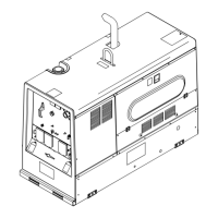
5-1. Installing Welder/Generator
Movement
OM-4410 Page 1
18 in
(460 mm)
18 in
(460 mm)
18 in
(460 mm)
18 in
(460 mm)
18 in
(460 mm)
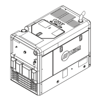
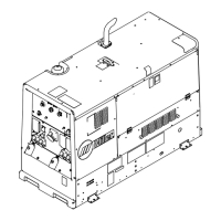
1-1. Installing Welder/Generator
1
Location/Airflow Clearance
Complete Parts List available at www.MillerWelds.com
OM-249336 Page 14
18 in
(460 mm)
18 in
(460 mm)
18 in
(460 mm)
18 in
(460 mm)
18 in
(460 mm)
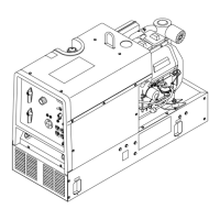
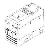
Mounting
OM-4410 Page 1
18 in
(460 mm)
18 in
(460 mm)
18 in
(460 mm)
18 in
(460 mm)
18 in
(460 mm)
1-1. Installing Welder/Generator
1
Do not move or operate unit where
it could tip.
Do not lift unit from end.
Do not weld on base. Welding on
base can cause fuel tank fire or ex-
plosion. Bolt unit down using
holes provided in base.
Always securely fasten welding
generator onto transport vehicle or
trailer and comply with all DOT and
other applicable codes.
NOTICE – Do not install unit where airflow is
restricted or engine may overheat.
F
See Specifications for lifting eye rating.
Mounting:
Do not mount unit by supporting
the base only at the four mounting
holes. Do not use flexible mounts.
Use cross-supports to adequately
support unit and prevent damage
to base.
1 Cross-Supports
Mount unit on flat surface or use cross-sup-
ports to support base.
F
Go to MillerWelds. com for more infor-
mation on truck installations.
 Loading...