OM-286504 Page 28
F
Complete Parts List is available at www.MillerWelds.com
SECTION 6 – OPERATION
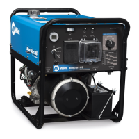
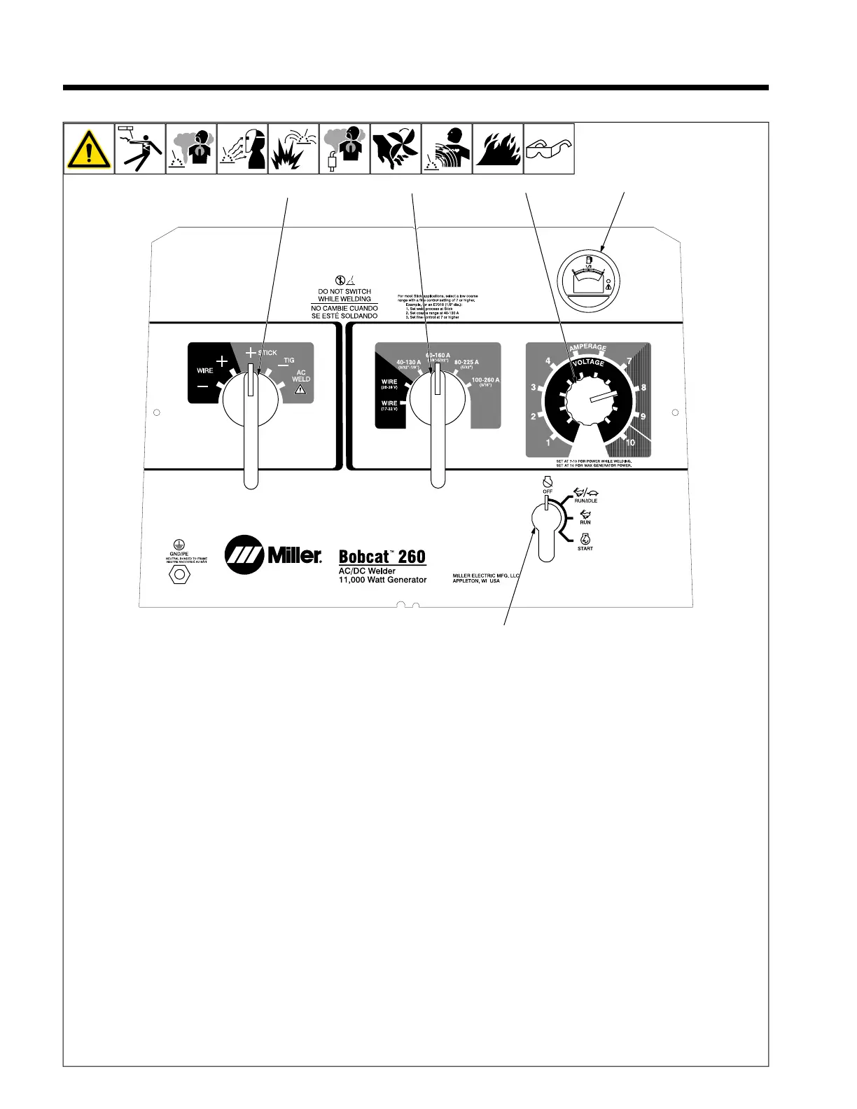
6-1. Front Panel Controls
1 Engine Control Switch
Use switch to start engine, select speed,
and stop engine. In Run/Idle position, en-
gine runs at idle speed at no load, and weld/
power speed under load. In Run position,
engine runs at weld/power speed.
F
Place switch in Run position to operate
most MIG equipment.
Use control to change engine air-fuel mix.
To Start: pull out choke (LP engine only)
and turn Engine Control switch to Start posi-
tion. Release switch when engine starts.
Slowly push in choke (LP engine only).
F
If the engine does not start, let engine
come to a complete stop before at-
tempting restart.
F
During cold weather some gasoline en-
gines encounter difficulties that are
easily remedied. See Section 6-3 and
Troubleshooting Tables.
To Stop: turn Engine Control switch to Off
position.
2 Engine Hour Meter/Fuel Gauge/Idle
Control
Low fuel is indicated by an orange flashing
light on the right side of the display.
A maintenance interval is reached when the
wrench icon appears in the display.
Hour Meter: With engine off, place Engine
Control switch in Run/Idle position to view
engine hours.
Oil Change Interval: With engine off, place
Engine Control switch in the Run position to
see hours before next oil change. Oil hours
start at 100 and count down to 0 (zero) (oil
change due).
F
Negative hours indicated when past
recommended oil change interval.
To reset, cycle Engine Control switch from
Run/Idle to Run three times within five sec-
onds (engine off).
3 Weld Process Selector Switch
NOTICE – Do not switch under load.
Use switch to select type of weld output.
Wire (GMAW) Welding: Use a positive (+)
position for Direct Current Electrode Positive
(DCEP) and a negative (-) position for Direct
Current Electrode Negative.
Stick (SMAW) and TIG (GTAW Welding):
Use a positive (+) position for Direct Current
Electrode Positive (DCEP) and a negative
(-) position for Direct Current Electrode
Negative. Use AC position for alternating
current.
4 Coarse Range Switch
NOTICE – Do not switch under load.
Use switch to select weld amperage range
when Weld Process Selector switch is in
Stick/Tig position, or voltage range when
switch is in Wire position.
F
For best arc starts and when using
weld and generator power together,
use a low Coarse Range setting with
the Fine control set at 7 or higher.
5 Fine Control
Use control to select weld amperage (Stick/
Tig) or voltage (Wire) within the range se-
lected by the Coarse Range switch. Control
may be adjusted while welding.
Set control at 10 for maximum generator
power.
Weld output would be about 128 A DC
based on control settings shown (80% of 60
to 160 A). Settings shown are typical for
welding with a 7018 (1/8) electrode.
F
See Sections 6-4 thru 6-6 for typical
process connections and control
settings.
 Loading...