OM-286504 Page 53
SECTION 11 – GENERATOR POWER GUIDELINES
F
The views in this section are intended to be representative of all engine-driven welder/generators. Your unit may differ from those shown.
11-1. Selecting Equipment
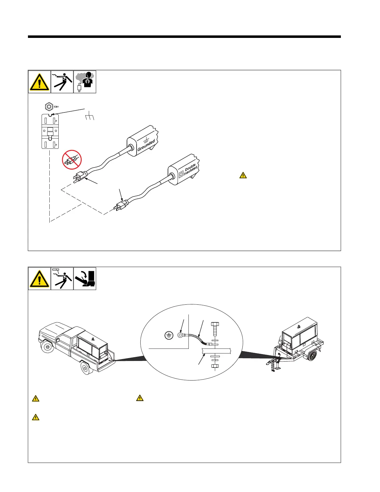
1 Generator Power Receptacles – Neutral
Bonded To Frame
2 3-Prong Plug From Case Grounded
Equipment
OR
3 2-Prong Plug From Double Insulated
Equipment
F
Be sure equipment has double insu-
lated symbol and/or wording on it.
Do not use 2-prong plug unless
equipment is double insulated.
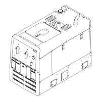
11-2. Grounding Generator to Truck or Trailer Frame
OM-236 948 Page 1
1-1. Grounding Generator To Truck Or Trailer Frame
1
3
2
GND/PE
Always ground generator frame to
vehicle frame to prevent electric
shock and static electricity hazards.
Also see AWS Safety & Health Fact
Sheet No. 29, Grounding of Portable
And Vehicle Mounted Welding
Generators.
Bed liners, shipping skids, and
some running gear insulate the
welding generator from the vehicle
frame. Always connect a ground
wire from the generator equipment
grounding terminal to bare metal on
the vehicle frame as shown.
1 Equipment Grounding Terminal (On
Front Panel)
2 Grounding Cable (Not Supplied)
3 Metal Vehicle Frame
Connect cable from equipment ground ter-
minal to metal vehicle frame. Use #8 AWG
or larger insulated copper wire.
F
Electrically bond generator frame to
vehicle frame by metal-to-metal
contact.
 Loading...