OM-286504 Page 34
F
Complete Parts List is available at www.MillerWelds.com
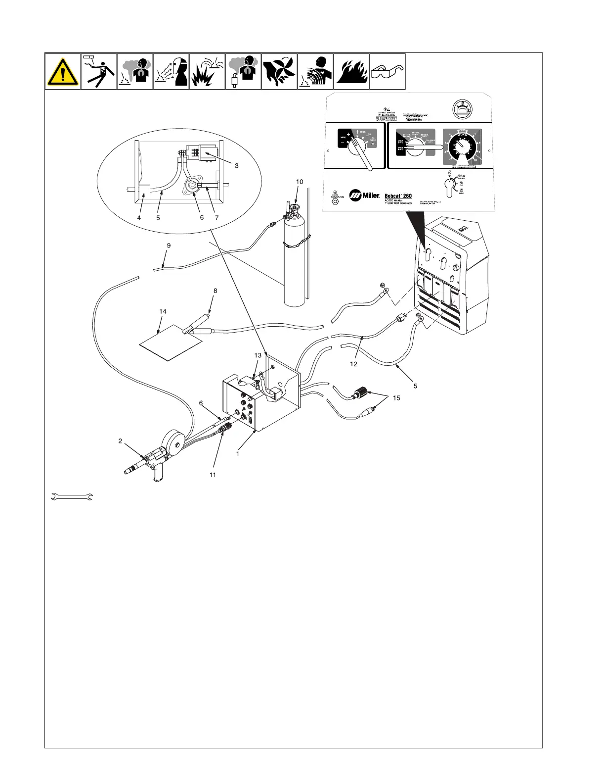
6-6. Typical MIG Connections And Settings Using Weld Control And Spoolgun
OM-222 Page 1
allen_wrench
NGO’s
tools/
flathead philips head wrench
pliers
knife
heavy-duty workclamp light-duty workclamp wirecutter frontcutter
allen_set
needlenose
steelbrush nutdriver
chippinghammer
solderiron
stripcrimp
drill
torque wrench
socket wrench
hammer awl file
crimper
paintbrush
feelergauge flashlight ruler
toothbrush
greasegun
qtip (swab)
vicegrip
handream
punch
filterwrench
strapwrench
airgun
solvent pinextractor eprompuller pipewrench
torque screwdriver
crescent wrench
3/4 in.
F
This section provides general guide-
lines and may not suit all applications.
1 Weld Control
2 Spoolgun
3 Optional Contactor (Recommended)
4 Reed Switch
5 Weld Cable (Customer Supplied)
6 Weld Control Weld Terminal
7 Weld Power Cable From Spoolgun
8 Work Clamp
9 Gas Hose
10 Argon Cylinder
11 Trigger Control Cord
12 Input Power Cord
13 Unused Contactor Terminal
14 Work
15 Plug And Sensing Lead (Not Used In
This Application)
F
Be sure to use the correct size weld
cables (see Section 5-9).
Route weld cable from welder/generator
Electrode terminal through reed switch to
unused contactor terminal. Connect weld
cable from spoolgun to weld control weld
terminal (item 6).
Connect work cable to welder/generator
Work terminal.
Insert trigger control plug (item 11) into weld
control receptacle. Tighten threaded collar.
Connect AC power cord (item 12) to 120 volt
AC receptacle on welder/generator.
Connect gas hose from spoolgun to regula-
tor on Argon bottle.
Reinstall weld control wrapper.
Typical Settings For 4043 (.035) Alumi-
num On 1/8 in. Material:
l Set Weld Process Selector switch to
Wire + (DCEP) position.
l Set Coarse Range switch to Wire (17-
22 volts) Range position.
l Set Fine Control to desired voltage (arc
length). Start with a low voltage setting
(about 4) to prevent burnback.
l Set wire feed speed between 240- 270
IPM. For 1/4 in. and thicker materials,
set Coarse Range switch to Wire/High
and Fine Control to 6. Increase/de-
crease Fine Control setting to increase/
decrease arc length.
F
Miller recommends Hobart filler
metals.
 Loading...