OM-286504 Page 33
F
Complete Parts List is available at www.MillerWelds.com
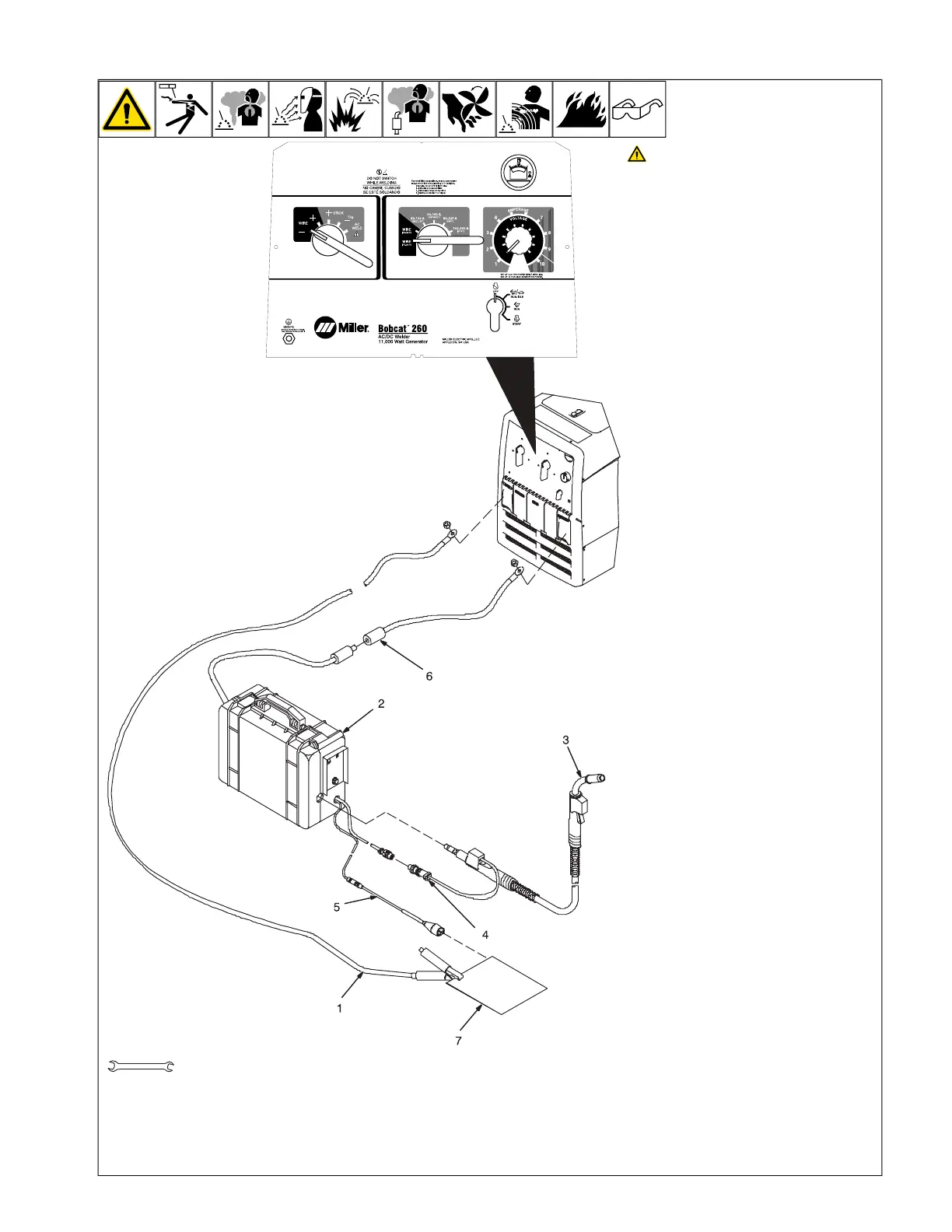
B. Self-Shielded Flux Core Wire Applications
OM-222 Page 1
allen_wrench
NGO’s
tools/
flathead philips head wrench
pliers
knife
heavy-duty workclamp light-duty workclamp wirecutter frontcutter
allen_set
needlenose
steelbrush nutdriver
chippinghammer
solderiron
stripcrimp
drill
torque wrench
socket wrench
hammer awl file
crimper
paintbrush
feelergauge flashlight ruler
toothbrush
greasegun
qtip (swab)
vicegrip
handream
punch
filterwrench
strapwrench
airgun
solvent pinextractor eprompuller pipewrench
torque screwdriver
crescent wrench
3/4 in.
Stop engine.
F
This section provides general guide-
lines and may not suit all applications.
F
The control panel shows the typical set-
tings for welding with .045 (71T-11)
self-shielded flux core wire. Note
Coarse Range, Fine Control, and Weld
Process switch settings.
1 Work Clamp
2 Wire Feeder
3 MIG Gun
4 Gun Trigger Plug
5 Voltage Sensing Clamp
6 Quick Connector
7 Workpiece
Connect work cable to welding generator
Work terminal. Connect cable from wire
feeder to cable from welding generator Elec-
trode terminal.
F
Be sure to use the correct size weld ca-
bles (see Section 5-9).
Loosen MIG gun securing knob. Insert gun
end through opening in feeder and position
as close as possible to drive rolls without
touching. Tighten knob.
See wire feeder manual for wire threading
procedure.
Insert gun trigger plug (item 4) into matching
receptacle and tighten threaded collar.
Typical Control Settings Using .045 (71T-
11) Self-Shielded Flux Core Wire :
l Set Weld Process Selector switch to
Wire - position (DCEN).
l Set Coarse Range switch to Wire (17-22
volts) Range position.
l Set Fine Control near minimum setting.
l Set wire feed speed between 125-200
IPM.
l Do a test weld. To increase arc length,
increase Fine Control setting. To short-
en arc length, reduce fine control setting
or increase wire feed speed.
F
Miller recommends Hobart filler metals.
 Loading...