OM-286504 Page 31
F
Complete Parts List is available at www.MillerWelds.com
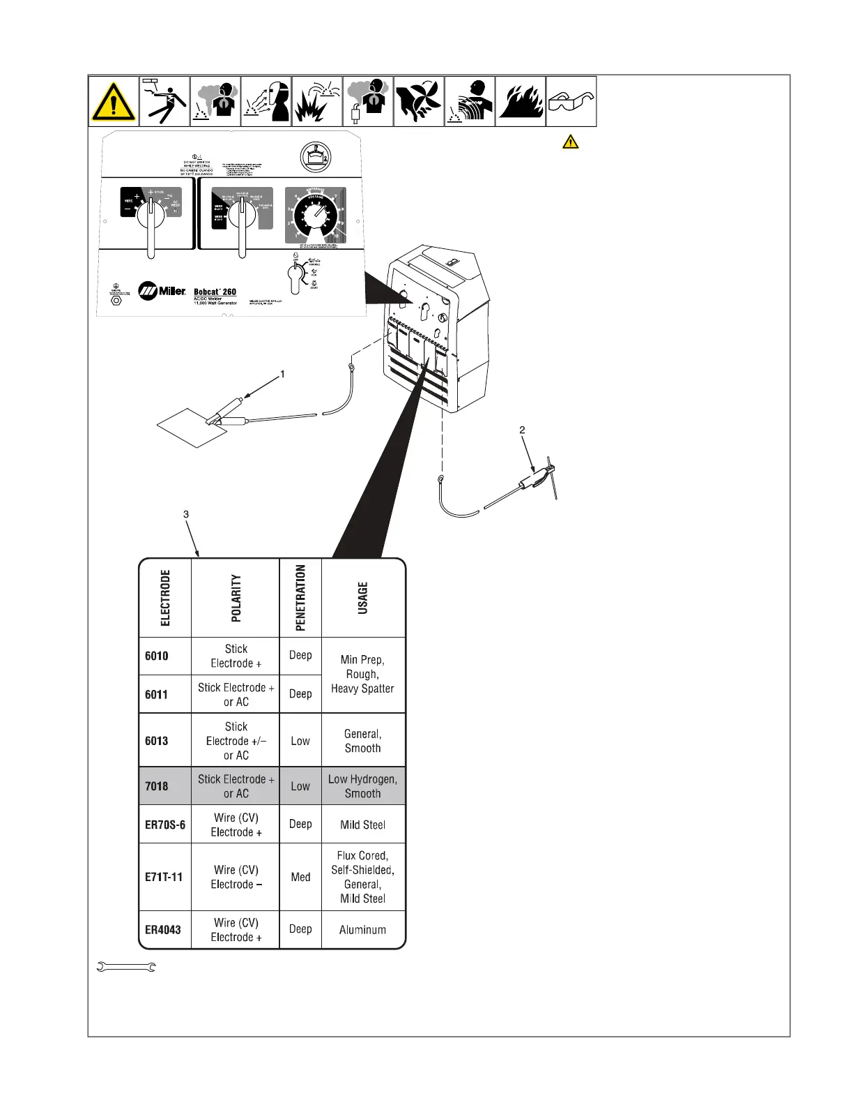
6-4. Typical Stick Welding Connections And Control Settings
OM-222 Page 1
allen_wrench
NGO’s
tools/
flathead philips head wrench
pliers
knife
heavy-duty workclamp light-duty workclamp wirecutter frontcutter
allen_set
needlenose
steelbrush nutdriver
chippinghammer
solderiron
stripcrimp
drill
torque wrench
socket wrench
hammer awl file
crimper
paintbrush
feelergauge flashlight ruler
toothbrush
greasegun
qtip (swab)
vicegrip
handream
punch
filterwrench
strapwrench
airgun
solvent pinextractor eprompuller pipewrench
torque screwdriver
crescent wrench
3/4 in.
Stop engine.
F
This section provides general guide-
lines and may not suit all applications.
F
The control panel shows the typical set-
tings for welding with a 7018 (1/8 in.)
electrode. Consult the amperage se-
lection tables below if welding with oth-
er electrodes.
1 Work Clamp
2 Electrode Holder
3 Electrode Selection Table (Beneath
Cover)
Connect Work cable to Work terminal and
Electrode holder cable to Electrode terminal
on welding generator.
F
Be sure to use the correct size weld ca-
bles (see Section 5-9).
F
For best performance, set the Coarse
Range switch to the lowest range that
covers the desired weld amperage.
Use the Fine control to select the de-
sired amperage within the range se-
lected. When properly set, the Fine
control is normally set at 7 or higher.
Typical Settings For 7018 (1/8 in.)
Electrode:
l Set Weld Process Selector switch to +
Stick position.
l Set Coarse Range switch to 60-160 (1/
8”) position.
l Set Fine control at 7 or higher for best
results.
F
Miller recommends Hobart filler metals.
 Loading...