OM-291417 Page 32
F
Complete Parts List is available at www.MillerWelds.com
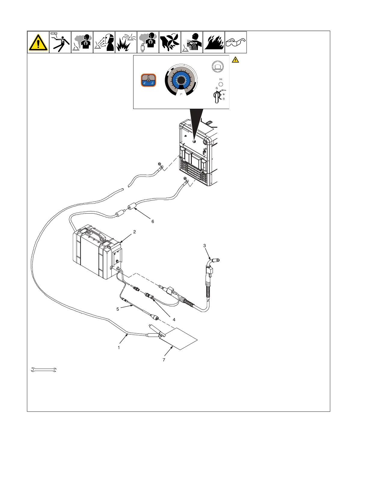
B. Self-Shielded Flux Core Wire Applications
CV
STICK
GAS NOGAS
CC – DCEP
DCEP DCEN
1/8"
3/32"
5
/
32"
20
40
60
80
100
120
140
160
180
260
30
50
70
90
110
130
150
170
190
14
20
21
22
23
24
25
26
27
28
15
16
17
18
19
200
210
220
230
240
250
3/1
6"
V
A
ELECTRODE
SIZE
265
CHOKE
OFF
RUN
RUN/IDLE
START
OM-222 Page 1
allen_wrench
NGO’s
tools/
flathead philips head wrench
pliers
knife
heavy-duty workclamp light-duty workclamp wirecutter frontcutter
allen_set
needlenose
steelbrush nutdriver
chippinghammer
solderiron
stripcrimp
drill
torque wrench
socket wrench
hammer awl file
crimper
paintbrush
feelergauge flashlight ruler
toothbrush
greasegun
qtip (swab)
vicegrip
handream
punch
filterwrench
strapwrench
airgun
solvent pinextractor eprompuller pipewrench
torque screwdriver
crescent wrench
3/4 in.
Stop engine.
F
This section provides general guide-
lines and may not suit all applications.
1 Work Clamp
2 Wire Feeder
3 MIG Gun
4 Gun Trigger Plug
5 Voltage Sensing Clamp
6 Quick Connector
7 Workpiece
Connect work cable to welding generator
Positive terminal. Connect cable from wire
feeder to cable from welding generator Neg-
ative terminal.
F
Be sure to use the correct size weld ca-
bles (see Section 5-9).
Loosen MIG gun securing knob. Insert gun
end through opening in feeder and position
as close as possible to drive rolls without
touching. Tighten knob.
See wire feeder manual for wire threading
procedure.
Insert gun trigger plug (item 4) into matching
receptacle and tighten threaded collar.
Typical Control Settings Using .045 (71T-
11) Self-Shielded Flux Core Wire :
l Set weld process selector to NO GAS.
l Set welding output between 15– 18
volts.
l Set wire feed speed between 105– 195
IPM.
l Do a test weld. To increase arc length,
increase voltage. To shorten arc length
reduce voltage or increase wire feed
speed.
F
Miller recommends Hobart filler metals.
 Loading...