OM-291417 Page 55
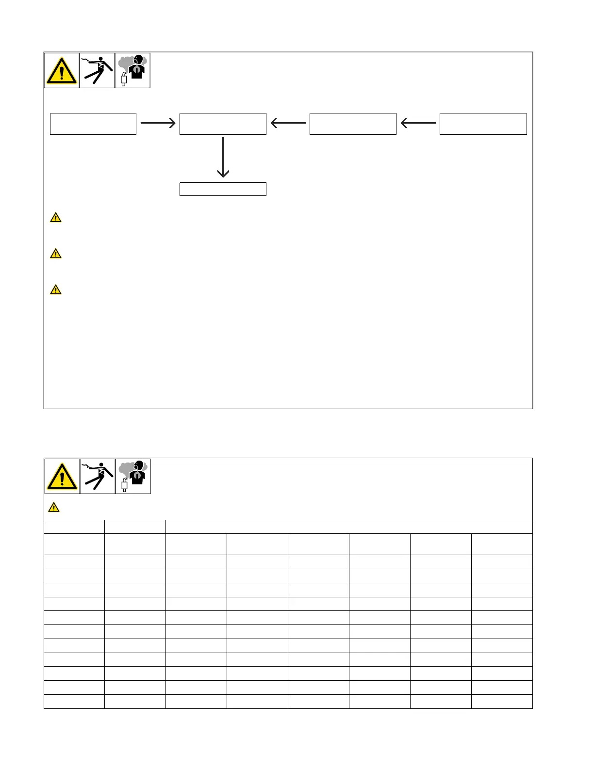
11-9. Typical Connections To Standby Power
1. Utility Electrical
Service
2. Transfer Switch 3. Fused Disconnect
Switch (If Required)
4. Welder/Generator
Output
5. Essential Loads
Have only qualified persons perform
these connections according to all
applicable codes and safety
practices.
Properly install, ground, and operate
this equipment according to its
Owner’s Manual and national, state,
and local codes.
Do not connect to any electrical dis-
tribution system normally supplied
by utility power unless a proper
transfer switch and grounding pro-
cedure are employed.
F
Customer-supplied equipment is re-
quired if generator will supply standby
power during emergencies or power
outages.
1 Utility Electrical Service
2 Transfer Switch (Double-Throw)
Switch transfers the electrical load from
electric utility service to the generator.
Transfer load back to electric utility when
service is restored.
Install correct switch (customer-supplied).
Switch rating must be same as or greater
than the branch overcurrent protection.
3 Fused Disconnect Switch
Install correct switch (customer-supplied) if
required by electrical code.
4 Welder/Generator Output
Generator output voltage and wiring must
be consistent with regular (utility) system
voltage and wiring.
Connect generator with temporary or perma-
nent wiring suitable for the installation.
Turn off or unplug all equipment connected
to generator before starting or stopping en-
gine. When starting or stopping, the engine
has low speed which causes low voltage
and frequency.
5 Essential Loads
Generator output may not meet the electri-
cal requirements of the premises. If genera-
tor does not produce enough output to meet
all requirements, connect only essential
loads. See Section 11-3.
11-10. Selecting Extension Cord (Use Shortest Cord Possible)
A. Cord Lengths For 120 Volt Loads
Use GFCI protection when operating auxiliary equipment. If unit does not have GFCI receptacles, use GFCI-protected extension
cord. Do not use GFCI receptacles to power life support equipment.
Maximum Allowable Cord Length In ft (m) for Conductor Size In AWG (mm
2
)*
Current
(Amperes) Load (Watts) 4 (25) 6 (16) 8 (10) 10 (6) 12 (4) 14 (2.5)
5 600 350 (106) 225 (68) 137 (42) 100 (30)
7 840 400 (122) 250 (76) 150 (46) 100 (30) 62 (19)
10 1200 400 (122) 275 (84) 175 (53) 112 (34) 62 (19) 50 (15)
15 1800 300 (91) 175 (53) 112 (34) 75 (23) 37 (11) 30 (9)
20 2400 225 (68) 137 (42) 87 (26) 50 (15) 30 (9)
25 3000 175 (53) 112 (34) 62 (19) 37 (11)
30 3600 150 (46) 87 (26) 50 (15) 37 (11)
35 4200 125 (38) 75 (23) 50 (15)
40 4800 112 (34) 62 (19) 37 (11)
45 5400 100 (30) 62 (19)
50 6000 87 (26) 50 (15)
*Conductor size is based on maximum 2% voltage drop.
 Loading...