OM-291417 Page 29
F
Complete Parts List is available at www.MillerWelds.com
SECTION 6 – OPERATION
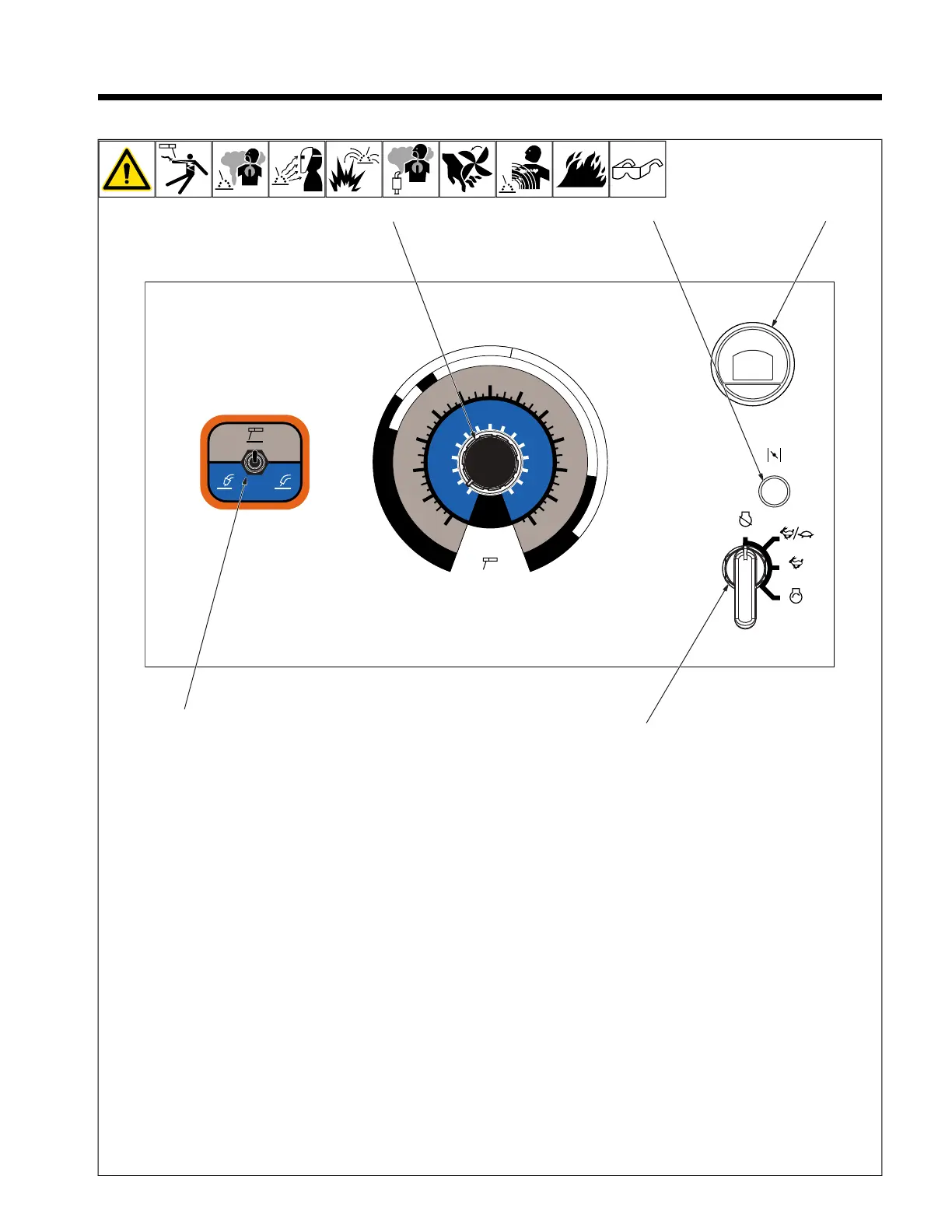
6-1. Dial Front Panel Controls
CV
STICK
GAS NO GAS
CC – DCEP
DCEP DCEN
1/8"
3/32"
5/32"
20
40
60
80
100
120
140
160
180
260
30
50
70
90
110
130
150
170
190
14
20
21
22
23
24
25
26
27
28
15
16
17
18
19
200
210
220
230
240
250
3/16"
V
A
ELECTRODE
SIZE
265
CHOKE
OFF
RUN
RUN/IDLE
START
1
2
3
4
5
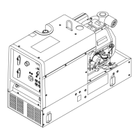
1 Engine Control Switch
Use switch to start engine, select speed,
and stop engine. In Run/Idle position, en-
gine runs at idle speed at no load, and weld/
power speed under load. In Run position,
engine runs at weld/power speed.
Engine will run at weld/power speed when
trigger is tapped on MIG equipment.
To Start: Pull out choke and turn Engine
Control switch to Start position. Release
switch when engine starts. Slowly push in
choke.
F
If the engine does not start, let engine
come to a complete stop before at-
tempting restart.
F
During cold weather some gasoline en-
gines encounter difficulties that are
easily remedied. See Section 6-5 and
Troubleshooting Tables.
To Stop: Turn Engine Control switch to Off
position.
2 Engine Hour Meter/Fuel Gauge/Idle
Control
Low fuel is indicated by a fuel icon flashing
in the center of the display.
A maintenance interval is reached when the
wrench icon appears in the display.
Hour Meter: With engine off, place Engine
Control switch in Run/Idle position to view
engine hours.
Oil Change Interval: With engine off, place
Engine Control switch in the Run position to
see hours before next oil change. Oil hours
start at 100 and count down to 0 (zero) (oil
change due).
F
Negative hours indicated when past
recommended oil change interval.
To reset, cycle Engine Control switch from
Run/Idle to Run three times within five sec-
onds (engine off).
3 Weld Process Selector Switch
Use switch to select type of weld output.
l CC
– STICK (SMAW)
l CV
– GAS/MIG (GMAW/FCAW) / NO
GAS (FCAW-S)
4 Volt/Ampere Setting
Use control to select weld amperage (CC) or
voltage (CV).
Ranges for common electrode sizes are
shown on exterior of dial.
F
See Sections 6-3 thru B. for typical
process connections and control
settings.
5 Choke
Used to control fuel flow during cold engine
starts.
 Loading...