OM-286308 Page 18
F
Complete Parts List is available at www.MillerWelds.com
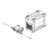
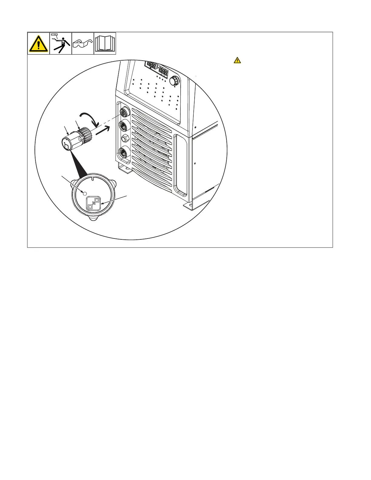
6-3. Connecting 14-Pin Transceiver To Remote Receptacle
OM-286308 Page 16
5-9. Connecting 14-Pin Transceiver To Remote 14 Receptacle
Ref. 804746-B / Ref. 805627-A
! Unexpected weld output can
cause electrical shock. Re-
mote controls can turn on
weld output from distant lo-
cations. Disconnect 14-Pin
Transceiver from remote 14
receptacle and remove the
batteries from the wireless
foot control and/or wireless
hand control before servic-
ing equipment.
Turn Off welding power source.
1 14-Pin Transceiver
2 Hand Threaded Nut
Insert the 14-Pin Transceiver into
the remote 14 receptacle on the
welding power source. Tighten the
Hand Threaded Nut by rotating
clockwise. Do not over tighten.
Turn welding power source on.
3 Wireless Status Light
Status Light Indication:
Solid Red = Not paired and/or lost
communication
Solid Green = Paired and communi-
cating
Solid Amber = Pairing mode,
searching for wireless remote
control
NOTICE To remove the 14-Pin
Transceiver, rotate hand threaded
nut counterclockwise.
1
3
2
4
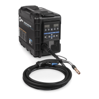
5-10. Wireless Foot Control Operation
! Unexpected weld output can
cause electrical shock. Wire-
less remote controls can turn
weld output on from distant
locations. Disconnect receiv-
er from remote 14 receptacle
and remove battery from re-
mote control before servicing
equipment.
1 Remote Foot Control
Use control to turn on output
contactor and control amperage
remotely.
This control does not override
welding power source contactor
and amperage panel settings.
Welding power source panel
settings:
Place output contactor control in
remote position.
Place amperage control in Remote
position.
1
Ref. 805625-A
Unexpected weld output can cause
electrical shock. Wireless remote
controls can turn on weld output
from distant locations. Disconnect
14-Pin Transceiver from remote 14
receptacle and remove the bat-
teries from the wireless foot con-
trol and/or wireless hand control
before servicing equipment.
Turn off welding power source.
1 14-Pin Transceiver
2 Hand Threaded Nut
Insert the 14-Pin Transceiver into the remote
14 receptacle on the welding power source.
Tighten the Hand Threaded Nut by rotating
clockwise. Do not over tighten. Turn welding
power source on.
3 Wireless Status Light
Status Light Indication:
Solid Red = Not paired and/or lost
communication.
Solid Green = Paired and communication.
Solid Amber = Pairing mode, searching for
wireless remote control.
NOTICE – To remove the 14-Pin Trans-
ceiver, rotate hand threaded nut
counterclockwise.