OM-286308 Page 20
7-2. Wireless Hand Control Operation
OM-286308 Page 17
5-11. Wireless Hand Control Operation
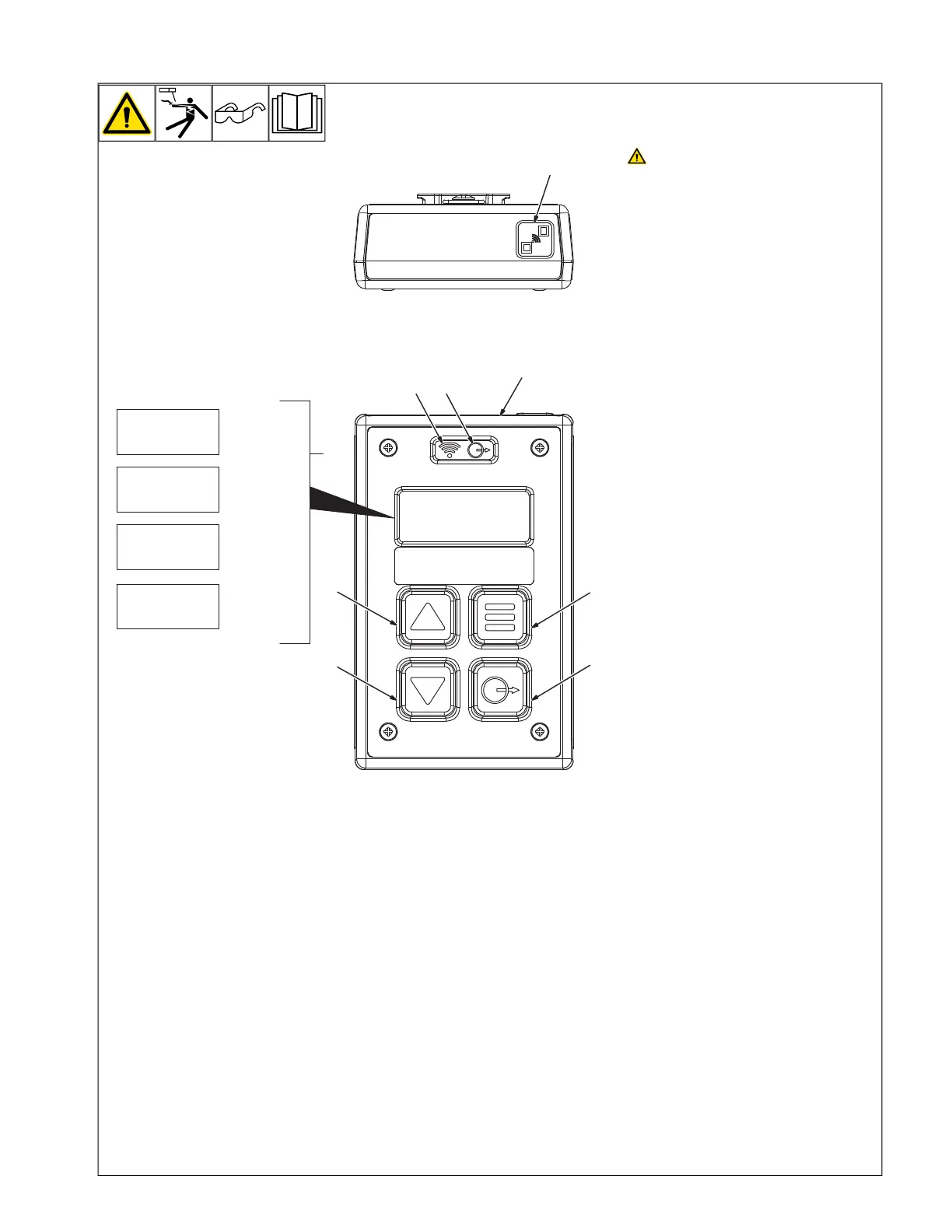
! Unexpected weld output can
cause electrical shock. Wireless
remote controls can turn weld out-
put on from distant locations. Dis-
connect 14-pin transceiver from
remote 14 receptacle and remove
the batteries from the wireless
foot control and/or wireless hand
control before servicing equip-
ment.
1 Wireless Hand Control
2 Pairing Button
3 Wireless Status Light Indication:
Wireless status light indication:
Solid Red = Not paired and/or lost com-
munication.
Flashing Green = Paired and communi-
cating.
Solid Amber = Pairing mode, searching
for 14-pin transceiver.
4 Contactor Output Control Button
5 Contactor Output Status Light
Contactor output status light indication:
Off = Contactor open, output off.
Solid Blue = Contactor closed, output on.
6 Increase Button
7 Decrease Button
Press and release the increase or
decrease button respectively to adjust in
1 percent increments. Press and hold the
increase or decrease button respectively
to adjust in 5 percent increments.
8 Menu Button
Press the menu button to select per-
centage, amperage, or voltage. The
selected parameter is shown on the
display screen.
Some welding power sources are not
equipped with amperage and voltage
feedback, and the wireless hand
control can be used to display am-
perage and voltage.
9 Display Screen
Displays selected parameter:
Percentage, Amperage or Voltage.
The display screen stays illuminated
while the contactor output status light is
Illuminated solid blue. To extend battery
life, the display screen, wireless status
light, and contactor output status light
turn off after 10 seconds of inactivity if the
contactor is open, output is off.
Displayed amperage and voltage
values are for reference only and
may not accurately reflect the true
amperage and voltage output value.
1
5
9
6
7
4
8
= Percentage
= Amperage
= Voltage
P
A
V
PAIR
= Pair Mode
Ref. 805626-A
Front
Top
3
2
Unexpected weld output can cause
electrical shock. Wireless remote
controls can turn on weld output
from distant locations. Disconnect
14-Pin Transceiver from remote 14
receptacle and remove the bat-
teries from the wireless foot con-
trol and/or wireless hand control
before servicing equipment.
1 Wireless Hand Control
2 Pairing Button
3 Wireless Status Light Indication:
Wireless Status Light Indication:
Solid Red = Not paired and/or lost
communication.
Solid Green = Paired and communicating.
Solid Amber = Pairing mode, searching for
14-Pin Transceiver.
4 Contactor Output Control Button
5 Contactor Output Status Light
Contactor output status light indication:
Off = Contactor open, output off.
Solid Blue = Contactor closed, output on.
6 Increase Button
7 Decrease Button
Press and release the increase or decrease
button respectively to adjust in 1 percent in-
crements. Press and hold the increase or de-
crease button respectively to adjust in 5
percent increments.
8 Menu Button
Press the menu button to select percentage,
amperage, or voltage. The selected parame-
ter is shown on the display screen.
F
Some welding power sources are not
equipped with amperage and voltage
feedback, and the wireless hand con-
trol can be used to display amperage
and voltage.
9 Display Screen
Displays selected parameter:
Percentage, Amperage or Voltage.
The display screen stays illuminated while
the contactor output status light is Illumi-
nated solid blue. To extend battery life, the
display screen, wireless status light, and
contactor output status light turn off after 10
seconds of inactivity if the contactor is open,
output is off.
F
Displayed amperage and voltage val-
ues are for reference only and may not
accurately reflect the true amperage
and voltage output value.