OM-286308 Page 26
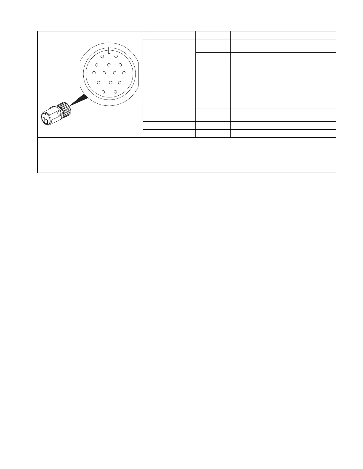
7-8. Transceiver 14-Pin Information
OM-286308 Page 23
5-17. Transceiver 14-Pin Information
A
J
B
K
I
C
L
N
H
D
M
G
E
F
Ref. 805627-A
Pin* Pin Information
OUTPUT
ENABLE
A Contactor control +15 volts DC / 24 volts AC, ref-
erenced to G.
B Contact closure to A completes and enables out-
put.
REMOTE
OUTPUT
CONTROL
C Output command voltage; 0-10 volts DC
D Remote control circuit common.
E Command percentage of Pin C with respect to Pin
D
A/V
AMPERAGE
VOLTAGE
F Current feedback; +1 volt DC per 100 amperes.
H Voltage feedback; +1 volt DC per 10 volts output.
COMMON
G Return for all output signals: F, H and A.
CHASSIS
K Chassis
Pins G and K
are electrically isloated from each other.
If a remote hand control, like the RHC-14, is connected to the Remote 14 receptacle, some current value above min. must be set on the remote
control before the Panel or Remote contactor is turned on. Failure to do so will cause current to be controlled by the panel control, and the
remote hand control will not function.
SECTION 6 TROUBLESHOOTING
6-1. Troubleshooting Table
Trouble Remedy
Remote completely inoperative. Red
wireless status light not lit on
transceiver.
Make sure power source is on.
Make sure receiver is connected properly to welding power source. (see Section 5-9)
Red wireless status light is on, but no
or limited control with remote, or con-
trols will not program.
Check and if necessary, replace batteries in remote hand or foot control.
Make sure components are properly paired. (see Section 5-14 and/or 5-15)
Make sure the controls are within working area, and without interferences.
Device will not pair. Move hand control or foot control within 1ft (25.4cm) of the receiver during pairing.
Remote 14 Socket Socket Information
Output Enable
A
Contactor control +15 volts DC / 24 volts AC,
referenced to G.
B
Contact closure to A completes and enables
output.
Remote Output
Control
C Output command voltage; 0-10 volts DC.
D Remote control circuit common.
E
Command percentage of Pin C with respect to
Pin D.
A/V Amperage
Voltage
F
Current feedback; +1 volt DC per 100 amps
output.
H
Voltage feedback; +1 volt DC per 10 volts
output.
Common G Return for all output signals: F, H and A.
Chassis K Chassis
Sockets G and K are electrically isolated from each other.
F
If a remote hand control like the RHC-14 is connected to the Remote 14 receptacle, some current value above min. must be set on the
remote control before the Panel or Remote contactor is turned on. Failure to do so will cause current to be controlled by the panel con-
trol, and the remote hand control will not function.