OM-356 Page 17
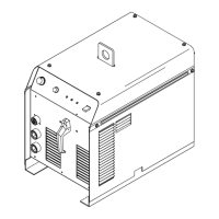
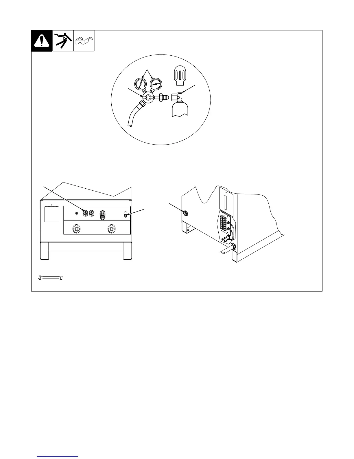
4-8. Shielding Gas Connections And 115 Volts AC Duplex Receptacle
Ref. ST-801 972-C / Ref. ST-801 973 / Ref. ST-157 858
Y Turn Off power before mak-
ing connections.
1 Gas Valve In Fitting
Located on rear of unit.
2 Gas Valve Out Fitting
Fittings have 5/8-18 right-hand
threads.
3 Cylinder Valve
Open valve slightly so gas flow
blows dirt from valve. Close valve.
4 Regulator/Flow Gauge
Connect regulator/flow gauge to
gas cylinder.
Connect customer supplied gas
hose between regulator/flow gauge
and gas in fitting.
5 Flow Adjust
Typical flow rate is 20 cfh (cubic feet
per hour).
6 115 V AC Receptacle
Receptacle is protected from over-
load by circuit breaker CB1 (see
Section 6-2).
5
1
6
4
2
5/8, 3/4, 1-1/8 in
Tools Needed:
3