OM-356 Page 20
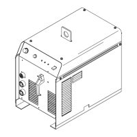
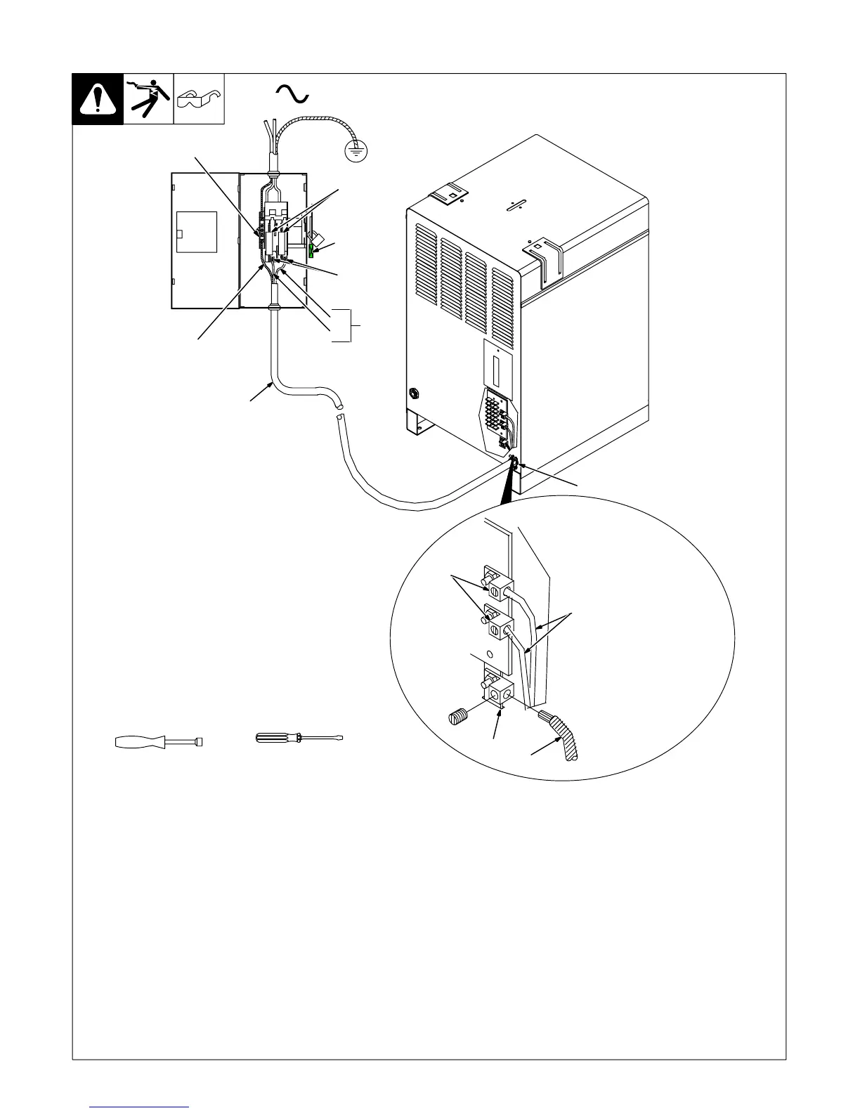
4-11. Connecting Input Power
Ref. ST-801 973-B
3/8 in
Tools Needed:
6
4
2
3
5
7
1
1
=GND/PE Earth Ground
4
8
9
10
L1
L2
6
Y Installation must meet all National and
Local Codes − have only qualified per-
sons make this installation.
Y Disconnect and lockout/tagout input
power before connecting input con-
ductors from unit.
Y Make input power connections to the
welding power source first.
Y Always connect green or green/yellow
conductor to supply grounding termi-
nal first, and never to a line terminal.
See rating label on unit and check input volt-
age available at site.
1 Input Power Conductors (Customer
Supplied Cord)
Select size and length of conductors using
Section 4-9. Conductors must comply with
national, state, and local electrical codes. If
applicable, use lugs of proper amperage
capacity and correct hole size.
Welding Power Source Input Power Con-
nections
2 Strain Relief
Route conductors (cord) through strain relief
and tighten screws.
3 Machine Grounding Terminal
4 Green Or Green/Yellow Grounding
Conductor
Connect green or green/yellow grounding
conductor to welding power source grounding
terminal first.
5 Welding Power Source Line Terminals
6 Input Conductors L1 And L2
Connect input conductors L1 and L2 to weld-
ing power source line terminals.
Close and secure access door on welding
power source.
Disconnect Device Input Power Connec-
tions
7 Disconnect Device (switch shown in
OFF position)
8 Disconnect Device (Supply) Grounding
Terminal
Connect green or green/yellow grounding
conductor to disconnect device grounding ter-
minal first.
9 Disconnect Device Line Terminals
Connect input conductors L1 and L2 to
disconnect device line terminals.
10 Overcurrent Protection
Select type and size of overcurrent protection
using Section 4-9 (fused disconnect switch
shown).
Close and secure door on line disconnect de-
vice. Remove lockout/tagout device, and
place switch in the On position.