9Installation, Operations & Maintenance Manual
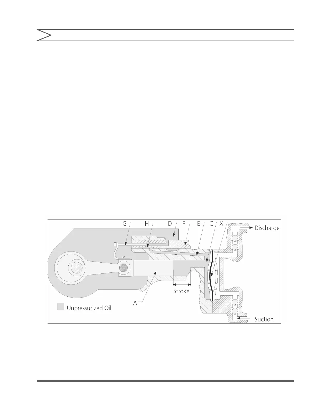
bypass port “H” as shown in Figure 2. Then the
balance of the plunger displacement is imposed on
the exible diaphragm that moves and displaces
the liquid being pumped through the discharge
ball checks.
On the suction stroke, the pump plunger pulls
oil out of the diaphragm cavity, which moves the
exible diaphragm and pulls liquid through the
suction ball checks. When the control plunger
“G” opens the bypass port “H” the balance of the
plunger oil displacement can be supplied from
the reservoir through the bypass passages. The
discharge capacity is adjusted from 0–100%
by rotating the adjustment knob that moves the
control spool valve “F” so that the bypass port “H”
is closed at the desired percentage of the total
plunger stroke. When the control spool valve is
adjusted to 100% capacity, the bypass port will be
positioned so that it is opened at the very end of
the suction stroke. Then on the pressure stroke,
the bypass port is immediately closed so the entire
plunger displacement is imposed upon the exible
diaphragm.
With the control spool valve adjusted for 50%
capacity, the bypass port will be positioned so that
it is opened when the plungers have completed
one-half of the suction stroke. On the next pressure
stroke, the oil displaced by the pump plunger will
be bypassed through the open port to the reservoir
for the rst 50% of the stroke, before the by-pass
port is closed by the control plunger. The remaining
50% of the plunger displacement will then be
imposed on the exible diaphragm so that liquid
is discharged for only 50% of the plunger travel. A
similar analysis would apply for 0% capacity setting
on the control spool valve where all the plunger oil
displacement is bypassed to the reservoir.
1.6 GENERAL SPECIFICATIONS
Figure 1. Pump Operation With By-Pass Port Open
SECTION 1 - GENERAL DESCRIPTION

 Loading...