58 Installation, Operations & Maintenance Manual
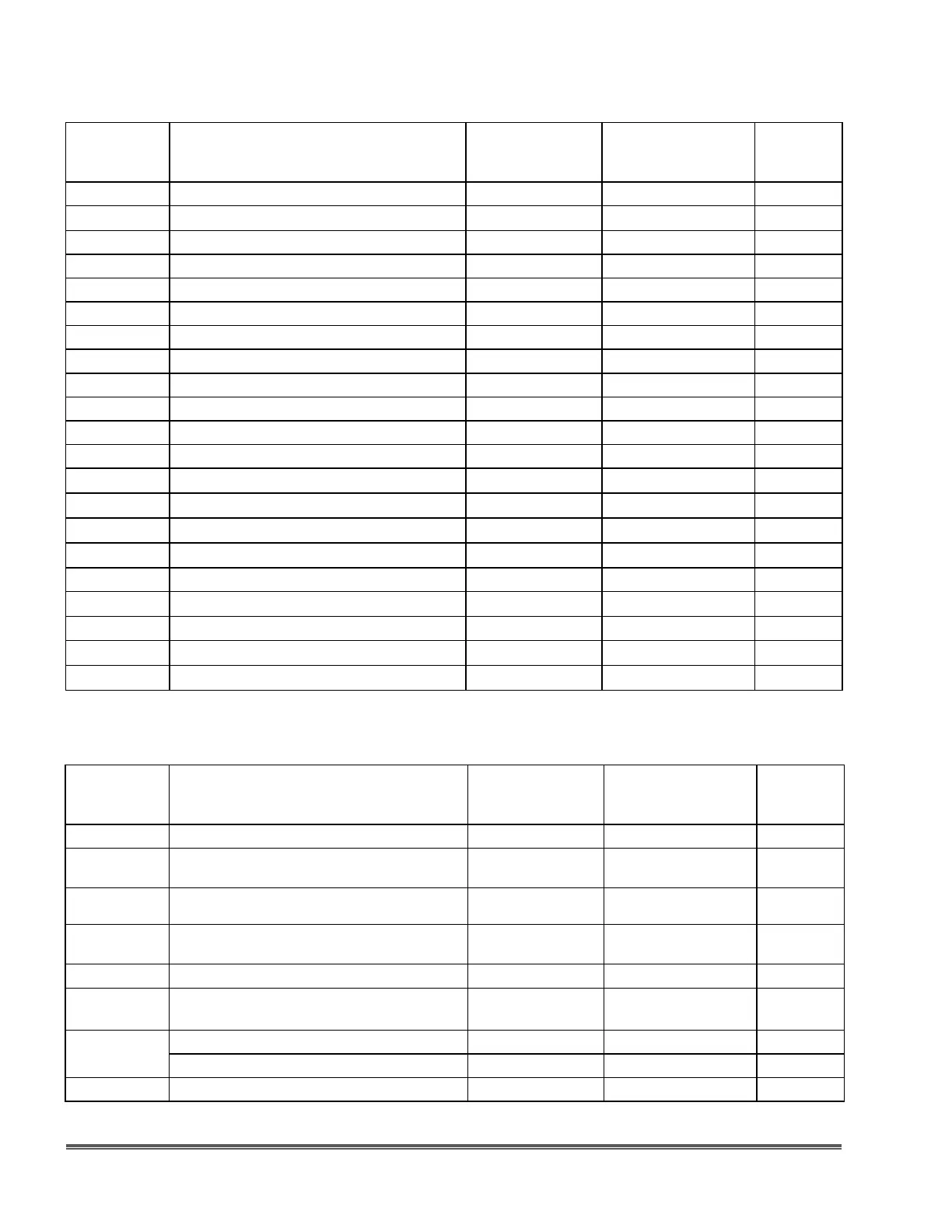
6.12 PNEUMATIC CAPACITY CONTROL (3-15 PSI DIRECT, FIGURE 23)
DRAWING
LOCATION
NUMBER
DESCRIPTION PART NUMBER MATERIAL/SPM QUANTITY
150 O-Ring, Parker - 2-011 408-0109-082 Polyurethane 3
215
Adapter 272-0052-017
1
220 E-Ring (1/4” for Control Knob) 404-0124-096 Steel 1
980 Flange, Mount mRoy A PCC 204-0070-062 Aluminum 1
990 O-Ring - 0.921 x 0.139 408-0095-041 NBR 1
1000 Lock-Washer, Int. Tooth - #6 404-0104-071 Steel, Zinc Plated 1
1010 Screw, Rd. Head - 6-32NC x 7/16 405-0002-061 Steel, Zinc Plated 1
1020 Screw, Slotted Shoulder - 5/16-18 405-0299-000 Steel 1
1030 O-Ring, Parker - 2-011 408-0109-082 Polyurethane 1
1040 Piston 212-0051-062 Aluminum 1
1050 O-Ring, - 2-226 408-0095-171 NBR 1
1060 Screw, - 1/4-20 x 1/2 405-0112-039 Steel, Zinc Plated 1
1070
Gasket, Pneumatic Cylinder 225-0073-098
1
1080
Cylinder, Pneumatic 281-0173-198
1
1090
Spring, Actuator 280-0041-000
1
1100
Gasket, Pneumatic Positioner 225-0030-098
1
1110 Stud 232-0010-106 Steel 6
1120
Postioner, Moore 403-0043-002
1
1130 Nut, Hex - 1/4-20NC 405-0064-012 18.8SS 6
1140
Decal, Pneumatic % Capacity 253-0029-198
1
1440
Mroy PCC Instruction Manual 339-0004-000
1
6.13 SIMPLEX LEAK DETECTION PARTS, FIGURE 22 (DOUBLE QUANTITIES FOR DUPLEX
PUMPS) (THIS PARTS LIST IS APPLICABLE ONLY TO mRoy E, F PUMPS, ALSO “V” CHECK
VALVE OPTION).
DRAWING
LOCATION
NUMBER
DESCRIPTION PART NUMBER MATERIAL/SPM QUANTITY
290 Diaphragm E & F plungers 298-0005-175 PTFE 2
300
Ring Assembly, Intermediate E & F 219-0127-000 316 SS
1
320
Contour Plate, Process Side 298-0091-016 316 SS
1
325
Contour Plate, Oil Side 298-0091-016 316 SS
1
350 Screw, Hex Head - 5/16-18 x 1-1/2 Gr5, 405-0017-149 Steel 6
355
Screw, Hex Head - 5/16-18 x 2-3/4 Gr5 405-0017-199 Steel
2
360
Base, Simplex Mroy A 201-0441-006 Steel 1
Base, Duplex Mroy A 201-0434-006 Steel 1
370 Screw, Hex Head - 5/16-18 x 1-1/4 Gr5 405-0017-139 Steel 3