24
Before applying power
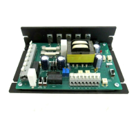
1. Set LINE VOLTAGE SELECT switches SW501 and SW502 to either 115V or 230V
to match the AC line voltage.
2. Set ARMATURE VOLTAGE SELECT switch SW503 to either 90V or 180V to
match the maximum armature voltage.
3. Set SIGNAL SELECT switch SW504 to CURR if using a 4-20 mADC current sig-
nal; set it to VOLT if using a 0-10VDC voltage signal or the speed adjust poten-
tiometer.
4. Verify that no conductive material is present on the printed circuit board.
5. If using a 90 VDC or 130 VDC motor with 230 VAC line voltage, derate the name-
plate motor torque by at least 30%. The form factor will increase beyond the typi-
cal value, causing increased motor heating. Contact the factory for details.
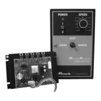
Chassis Drives (MM301U, MM311U)
Speed adjust potentiometer input, no START/STOP pushbutton:
It is necessary to wire a jumper between B1 and B3 if no START/STOP switches are
to be used.
1. Turn the speed adjust potentiometer full counterclockwise (CCW).
Operation
 Loading...