38
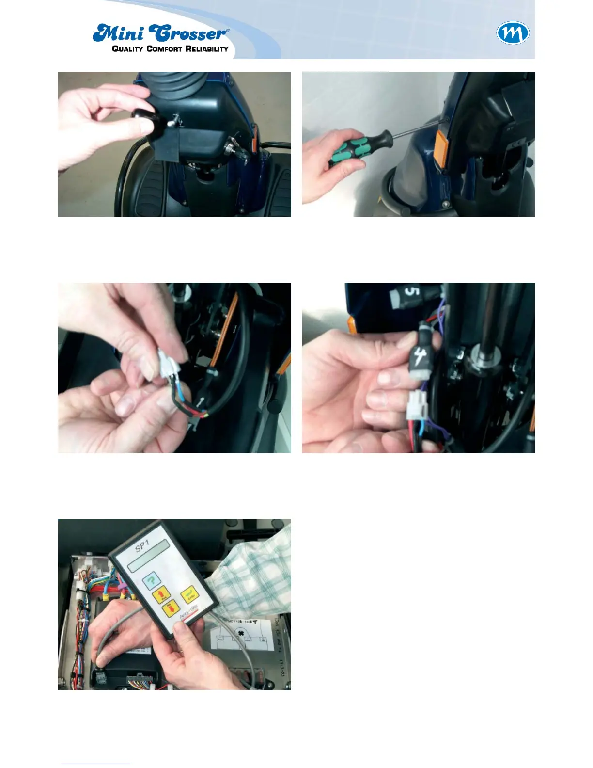
Figure 15: Insert the small crimps in the socket
so that the matching colours are
opposite each other.
Figure 16: Connect the foot pedal throttle to
socket number 4.
Figure 17:
Program the junction box to »single-ended«
input type. See separate description of pro-
gramming.
Switch on the scooter and check that the sole-
noid brake clicks when the throttle is activated.
When the throttle is released it should not be
possible to push the scooter.
It is important to install new plugs in the hole
for the side-view mirrors to ensure that the
handlebars are watertight. Use a couple of
drops of quick-drying glue.
Figure 13: Remove the plastic handle. Figure 14: Remove the plastic shroud by remo-
ving the six plastic screws.