42
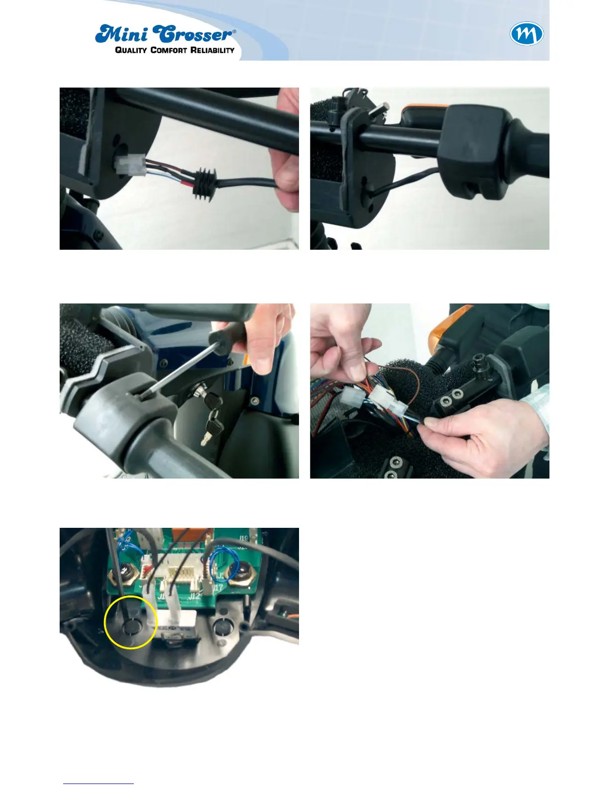
Figure 7: Install the electric plug and rubber
plug in the hole.
Figure 8: Install the twist grip on the handle-
bars.
Figure 9: Tighten the screws. Figure 10: Connect the twist grip to the three-
pin plug which the standard poten-
tiometer was connected to.
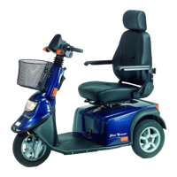
Figure 11: Install the forward/reverse switch.