43
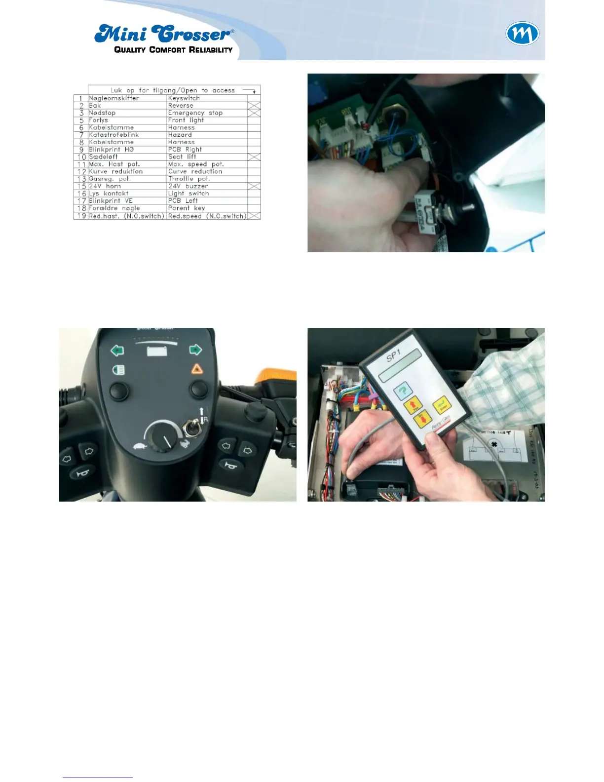
Figure 12: Figure 13: Connect to socket 2 on the PCB.
Insert the small crimps in the socket
so that the matching colours are
opposite each other.
Figure 14: Install the switch and place the
sticker as shown.
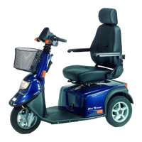
Figure 15: Program the junction box to »single-
ended« input type. See separate de-
scription of programming. Switch on
the scooter and check that the sole-
noid brake clicks when the throttle is
activated.
When the throttle is released it
should not be possible to push the
scooter.
It is important to install new plugs in
the hole for the side-view mirrors to
ensure that the handlebars are
watertight. Use a couple of drops of
quick-drying glue.