6.
NORME DI FUNZIONAMENTO • OPERATING PROCEDURES
ENGLISHITALIANO
- 142 -
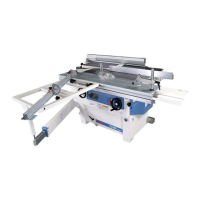
Tenonatura
La tenonatura è una fresatura di
testa (a traverso di vena) che vie-
ne effettuata per ottenere incastri
fra tenone maschio M (fig. 18) e
tenone femmina F.
Eseguire questa operazione con il
carro scorrevole, montando l’ap-
posito pianetto a tenonare A
(fig. 19).
Utilizzare l'apposita cuffia per
tenonare C.
Agire sui pomelli D e regolare le
protezioni E e F in modo da copri-
re al massimo l'utensile.
Nella versione con battute revesibili
(fig.20) sostituire il paraschegge H
come descritto nel cap.4 "montag-
gio pianetto a tenonare".
Bloccare sempre il pezzo
utilizzando il pressore in
dotazione.
La lavorazione di tenonatura va
eseguita esclusivamente con la
velocità di rotazione dell'albero
di 3500/4000 giri/min.
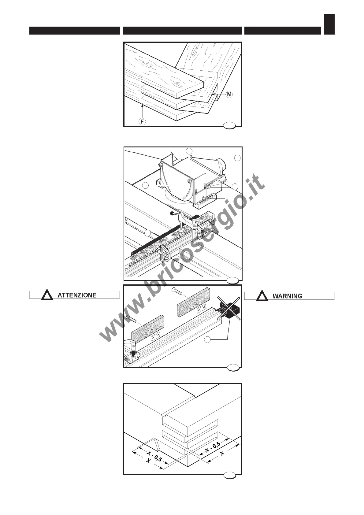
Per un migliore assemblaggio nel-
lo strettoio occorre:
– regolare la profondità dei tenoni
maschio 0,5 mm inferiori alla lar-
ghezza del montante (fig. 21);
– regolare la profondità dei tenoni
femmina 0,5 mm inferiori alla lar-
ghezza del traverso (fig. 21).
Tenoning
Tenoning is a head milling
operation (against the grain) which
is carried out to obtain joints
between male tenons M (Fig. 18)
and female tenons F.
Carry out this operation with sliding
table after fitting additional table A
(fig. 19).
Use the appropriate tenoning hood
C.
Act on the knobs D and adjust the
protections E and F so that they
cover the tool as much as
possible.
In the version with reversible stops
(fig. 20) substitute the chip guard
H as described in chapter 4
“tenoning and table assembly".
Always lock the piece using the
presser provided.
Tenoning must exclusively be
carried out with a spindle rotation
speed of 3500/4000 rpm.
For a better assembly:
– adjust the tenon depth 0,5 mm
less than the jamb width (fig. 21);
– adjust the slot depth 0,5 mm less
than the crosspiece width
(fig. 21).
40_071_0.tif
18
21
63_067_0.tif
033.008.0.tif
20
H
033.040.0.tif
•
•
E
•
D
C
A
F
19