1177-02
PLOTDATUM : B-Stand : 001 / Ri. / 12.12.07 [002 / kupe / 12.12.07]12.12.2007
-K1
-X1
-G1
24 V
-X1
-K1
-G2
-G2.X3:-G2.X2:-G2.X4:
-G2.X1:
-S3
-S4
-K1
-X25 -X26
-X27
-X31
-Y1
-A1
-A1.X9:
-A1.X8:
-A1.X21: -A1.X34:
-A1.X20:
-A1.X4:
-A1.X22:
-A1.X1: -A1.X2:
-A1.X11:
-X18
-M7
-X19 -X24
-X12
-S7
-M3
-M4
-X32
-M2
-R1
-M3.S1
θ
-M4.S1
θ
-A2
-A2.X1:
-A2.X7:
-A2.X5: -A2.X6:
-X8
-X8
-X9
-X9
-S1
-M1
-M1.S1
θ
-S5
-S6
-A3
99-7036-50
-S11
-M1.Y1
-X17
-M1.S2
-X10
Blatt:Blattzahl:Normgepr.
Datum Name
Gezeichnet
Geprüft
NameDatumÄnd.-Nr.Nr.
VES-Nr. :
Ersatz für :
Änd. Nr. :
Benennung
Typ:
Zeichnungs-Nr.
Hako-Werke GmbH
D-23840 Bad Oldesloe
21
05.11. kupe12.12.07 Ri.
2007
0 Eingeführt lt.
A1
10
2
1
P
P(+)
N(-)
N
10
4
3
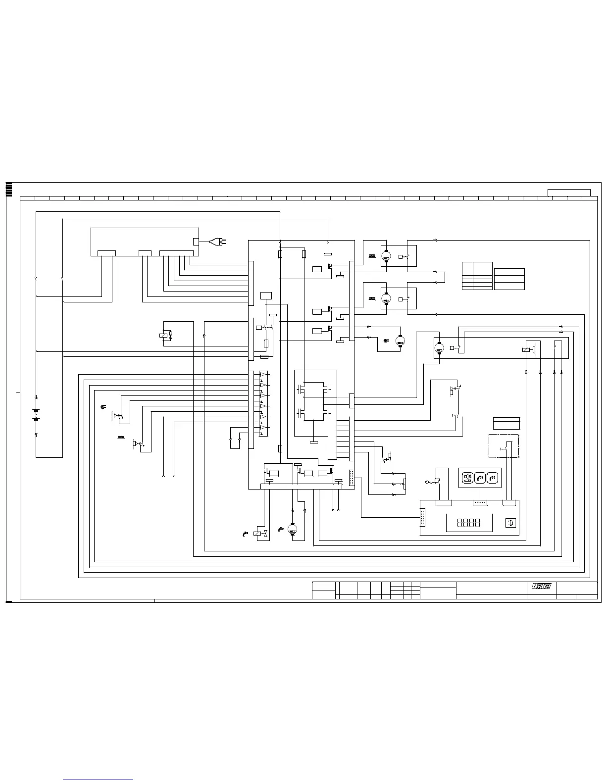
on-board-charger
supply main
1 2 12 123456
suction on
1
24
brush on
1
24
A1
A2
11
1
connected (state of deliver):
battery type Gis (wet)
disconnected:
battery type GiV (dry)
battery select
12
water valve
1
2
controller
3
10
4
11
1
8
2
9
5
12
6
13
F1
125A
2
4
3
1
1
2
5
7
4
6
8
3 1
2
3
4
5
6
1
2
1
2
3
4
5
6
7
8
F2
50A
LOGIC
F6
10A
F5
2A
LOGIC
LOGIC
LOGIC
38 49 16510
LOGIC LOGIC
27
7
14
LOGIC
VCC2
F3 5A
1
water
pump
RD
BK
112
1
2
brush
motor
left
brush
motor
right
dead man
switch right
C
NCNO
1
3
2
suction motor
GY
BK
+
-
speed giver
control panel
21 12
drive-
motor
1
2
1
2
key switch
BAT
BK
RD
forward
reverse
dead man
switch left
C
NO NC
2
13
direction switch
key
board
cable
marking
-M3:1
-M3:2
-M4:1
-M4:2
+
-
motor connection
conical brush
-M3:N
-M3:P
-M4:P
-M4:N
0 1
option
spray tool
spay tool on
connection conical brush
at motor -M3/4
binder plug topside
connection N
binder plug below
connection P
213
1
2
4
91026906
91026906
=
+
connec. scheme E 33 / Ph 35
-
-
-
-
-
-
-
-
-
M
M
M
M
M
Für diese Zeichnung behalten wir uns alle Rechte vor.(Gemäß DIN 34) 7311-23/-24
1 2 3 4 5 6 7 8 9 1011121314151617181920212223242526272829303132333435363738 39
Zahl kommt vor
0,1
0