FX-2000 User Guide
20
Unbypassing an active device/circuit
When you unbypass a device or circuit that went into alarm while it was bypassed, you will see the
following message:
If you select “yes” to unbypass this device, the system will immediately go into alarm. To avoid this
problem, press the System Reset button before unbypassing a device or circuit.
Loop Bypass
Use this option if you want to bypass an entire loop of addressable devices from the panel. Usually
this is done during building maintenance.
To unbypass the loop, follow the same procedures for loop bypass.
At this point the display will vary, depending on your choice:
• If you selected “yes”, the display will either show the message “Loop bypassed” or “Loop
unbypassed”, then return to the Command Menu.
• If you selected “no”, the display will show the message “Operation cancelled” and will then
return to the Command Menu.
WARNING: Bypassing a loop will disable all input and output devices in that loop.
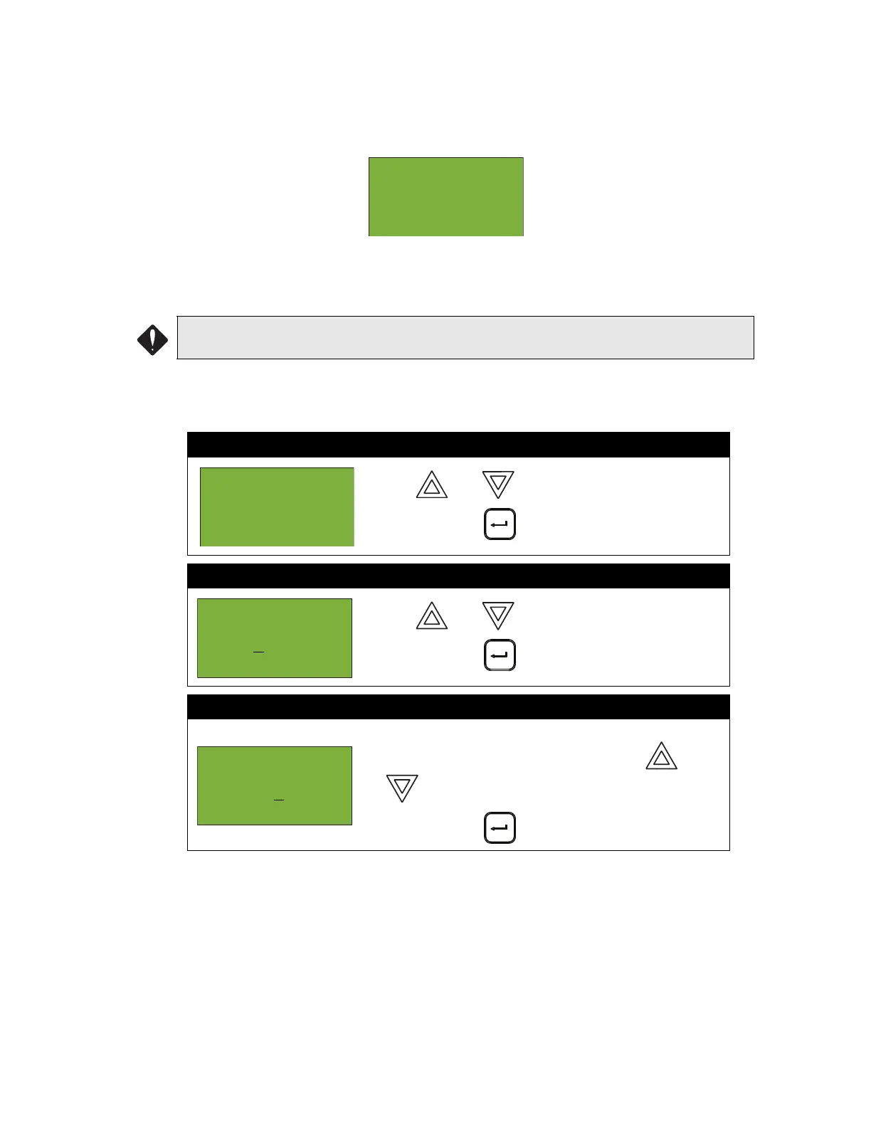
Step 1: Select Loop Bypass
1. Use and to scroll the to “Loop”.
2. Press ENTER ( ) to continue.
Step 2: Select a loop number
1. Use and to select the loop number.
2. Press ENTER ( ) to continue.
Step 3: Bypass the loop
1. The systems now asks you whether or not you would
like to bypass or unbypass the loop. Use and
to select “yes” or “no”.
2. Press ENTER ( ) to continue.
Warning: This
output
device is active.
Do you really
- Bypass Menu
-
1 Device /
Circuit
-Select Loop
Number -
Loop: 0
Loop 0 currently
not bypassed
Bypass? Y

 Loading...


