EasyManuals Logo

Mircom FX-2000 series User Manual

Mircom FX-2000 series
109 pages
To Next Page IconTo Next Page
To Previous Page IconTo Previous Page
Page #14 background imageLoading...
Page #14 background image
11
System Components
3.6 Batteries
The following table describes the batteries used with the FX-2000.
3.7 FX-2000 Accessories
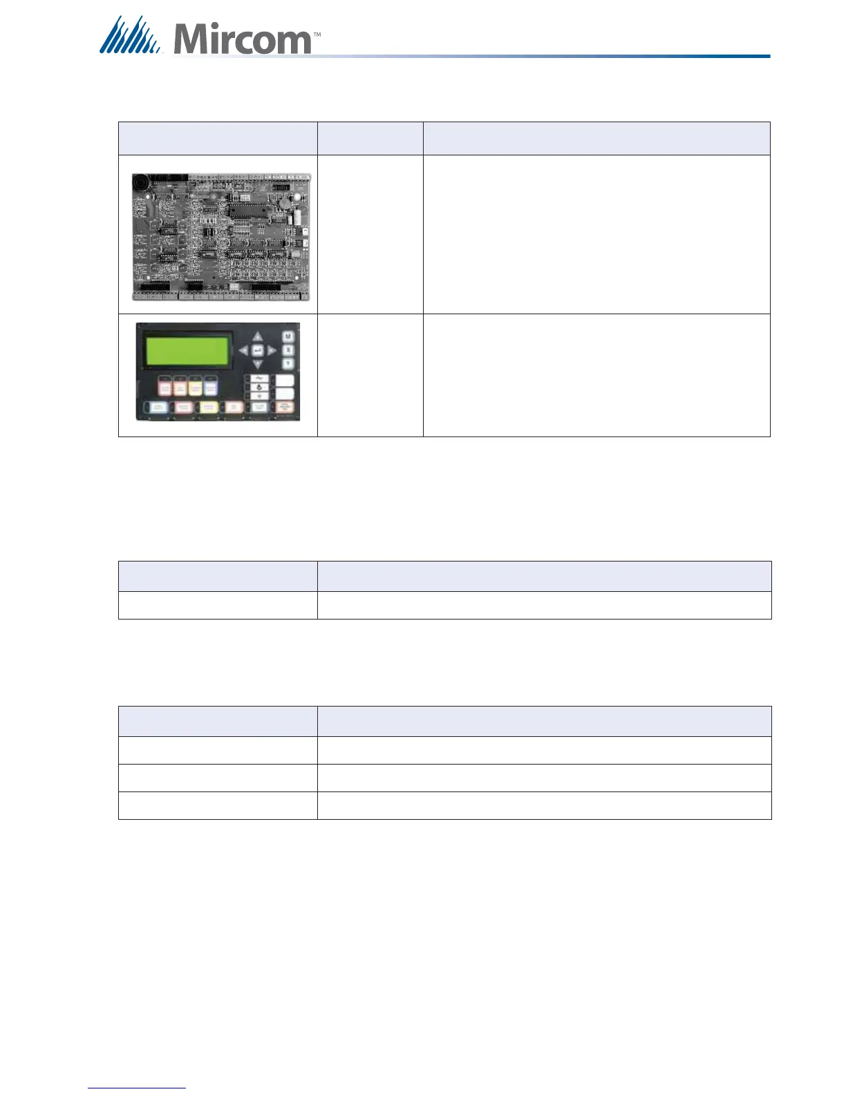
MGD-32,
AGD-048
Remote graphic annunciator drivers. The AGD-048
must be installed in the same enclosure as the
MGD-032.
RAX-LCD Remote Shared Display Annunciator
Table 7 Batteries
Model Description
Batteries 10 to 55 AH
Table 8 Accessories
Model Description
MP-300/R/S End-of-line Resistor Plate, Beige, R for red, S for stainless steel finish
RTI-1 Remote Trouble Indicator (ULC and ULI listed)
BC-160 External Battery Cabinet (ULC and ULI listed)
Table 6 FX-2000 Remote Annunciators
Model
Description

Table of Contents

Other manuals for Mircom FX-2000 series

Questions and Answers:

Question and Answer IconNeed help?

Do you have a question about the Mircom FX-2000 series and is the answer not in the manual?

Mircom FX-2000 series Specifications

General IconGeneral
TypeFire Alarm Control Panel
DisplayLCD
NetworkOptional
CommunicationRS-232, RS-485
ProgrammingVia keypad or PC
SLC Loops1
NAC Outputs4
Communication (Additional)Optional Ethernet
Input Voltage120 VAC or 240 VAC, 50/60 Hz
Battery Charging Current1.5 A
Auxiliary Power Output24 VDC
Operating Temperature0°C to 49°C (32°F to 120°F)
Relative HumidityUp to 93% non-condensing

Related product manuals