34
Module Settings
steady amber based on feedback from the monitor module that one or more of the fans is not
working.
ON LED shows steady for all outputs operating and confirmed.
OFF LED shows steady for all outputs NOT operating and confirmed.
TRBL LED shows steady for one or more outputs NOT operating and confirmed.
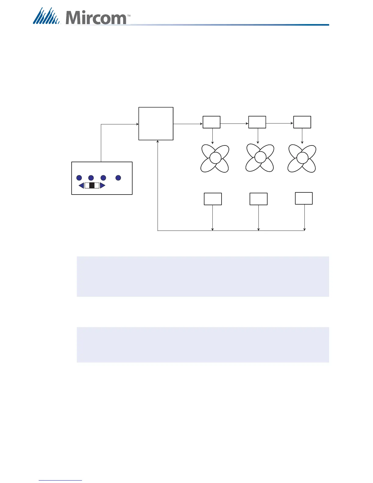
Figure 21 FDX-008W Block Diagram of Fan and Monitor Setup
Before mounting the FDX-008WKI module, if a keyswitch is to be connected, wire the
keyswitch to terminals at TS1 as shown in Figure 22 on page 35.
Note: A bypass function always has priority, so that if a circuit is bypassed by moving
the switch manually or by loop bypass (FX-2000 Fire Alarm Panel), no other
action will operate this switch other then again moving the switch manually or by
un-bypassing the loop.
Note: There are also terminals located behind TS1 on the other side of the board for
the convenience of wiring the keyswitch. The last fan damper zone in the bottom
right position of the FDX-008WKI is controlled by the keyswitch.
OFF AUTO ON TROUBLE
FX-2000 FIRE
ALARM PANEL
FANS
OUTPUT MODULES
MONITOR MODULES
FDX-008W/WKI FAN/DAMPER CONTROL MODULE