EasyManuals Logo

Mircom FX-2000 series User Manual

Mircom FX-2000 series
109 pages
To Next Page IconTo Next Page
To Previous Page IconTo Previous Page
Page #38 background imageLoading...
Page #38 background image
35
Module Settings
Mount the FDX-008W and FDX-008WKI Fan Damper Control Display modules in any position
on the front part of the FX-2000 chassis.
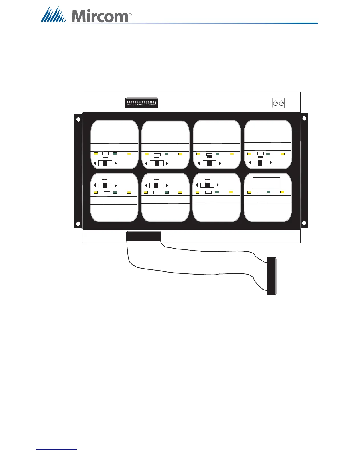
Figure 22 FDX-008WKI Fan Damper Control Display Module
OFF AUTO ON TROUBLE
OFF AUTO ON TROUBLE
OFF AUTO ON TROUBLE
OFF AUTO ON TROUBLE
OFF AUTO ON TROUBLE
OFF AUTO ON TROUBLE
OFF AUTO ON TROUBLE
OFF AUTO ON TROUBLE OFF AUTO ON TROUBLE
TS1
P2
TERMINALS AT TS1 ARE WIRED TO A KEYSWITCH.
NOTE: IF FAN DAMPER MODULE IS MOUNTED TO
THE DOOR USE TERMINALS LOCATED AT THE
BACK OF THIS BOARD, BEHIND TS1.
P1
KEYSWITCH
CONTROLLED
CONNECTS TO
PREVIOUS DISPLAY
MODULE P2

Table of Contents

Other manuals for Mircom FX-2000 series

Questions and Answers:

Question and Answer IconNeed help?

Do you have a question about the Mircom FX-2000 series and is the answer not in the manual?

Mircom FX-2000 series Specifications

General IconGeneral
TypeFire Alarm Control Panel
DisplayLCD
NetworkOptional
CommunicationRS-232, RS-485
ProgrammingVia keypad or PC
SLC Loops1
NAC Outputs4
Communication (Additional)Optional Ethernet
Input Voltage120 VAC or 240 VAC, 50/60 Hz
Battery Charging Current1.5 A
Auxiliary Power Output24 VDC
Operating Temperature0°C to 49°C (32°F to 120°F)
Relative HumidityUp to 93% non-condensing

Related product manuals