EasyManuals Logo

Mircom FX-2000 series User Manual

Mircom FX-2000 series
109 pages
To Next Page IconTo Next Page
To Previous Page IconTo Previous Page
Page #57 background imageLoading...
Page #57 background image
54
Field Wiring
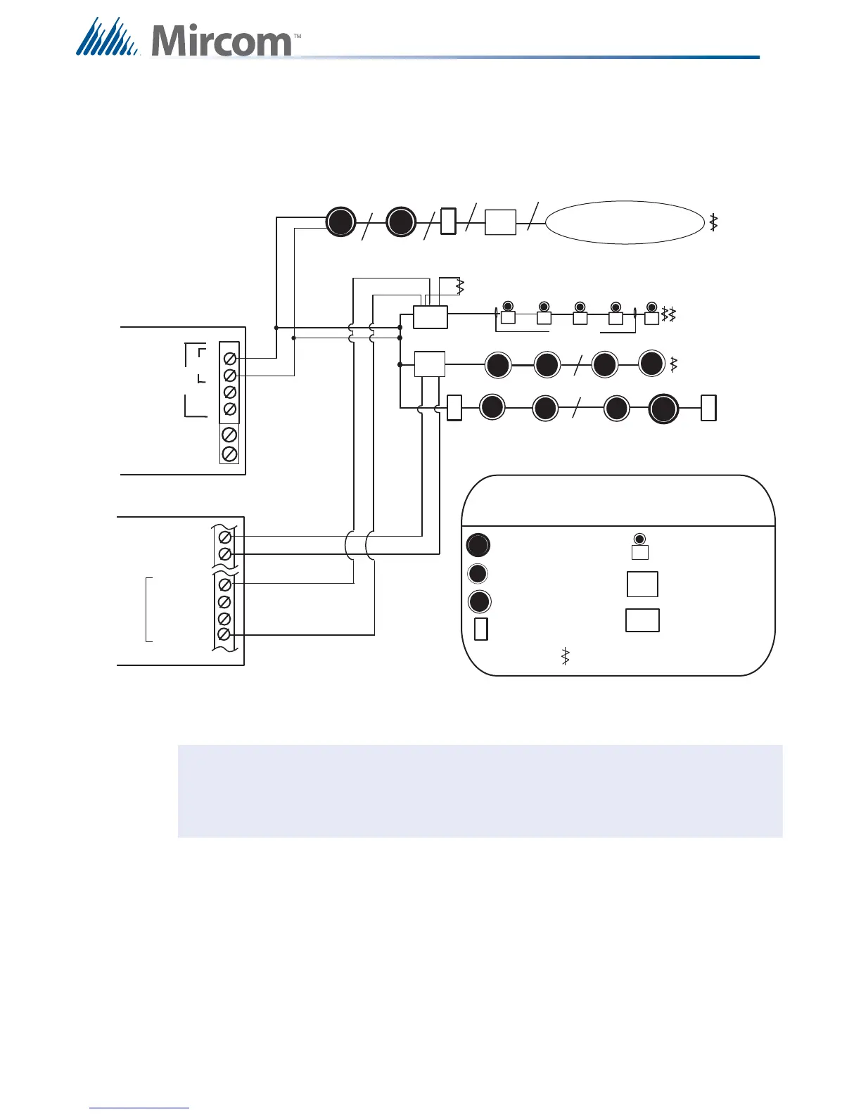
8.2.4 Single Loop Terminal Connections - Class B
Figure 36 Single Loop Terminal Connections - Class B
Notes: All power limited circuits must use type FPL, FPLR, or FPLP power limited cable.
Loop wiring: maximum loop resistance is 40 ohms total. These lines are fully
supervised.
Conventional Heat Sensors
and Manual Pull Stations
2 Pair
4-WIRE
RESETTABLE
SUPPLY
+
-
IND1 + (Y/Z)
IND1 + (Z)
IND1 - (Z)
IND1 - (Y/Z)
F
LEGEND
Addressable Smoke Sensor
with Standard Analog Base
Addressable Thermal Sensor
with Standard Analog Base
Conventional Smoke
Sensor
Addressable Manual
Pull Station
Combination
Horn/Strobe
Addressable
Monitor Module
Addressable Supvr.
Output Module
End-Of-Line-Resistor
TWO WIRES
TWO WIRES
S
H
S
C
s
C
s
C
s
F
F
H H
S
S
H
C
s
C
s
F
M
SO
M
TWO WIRES
M
SO
B
A
ANALOG
LOOP A
+
-
+
-
SHIELD
FX-2000
MAIN FIRE ALARM BOARD
ALC-198S SINGLE
LOOP MODULE
i

Table of Contents

Other manuals for Mircom FX-2000 series

Questions and Answers:

Question and Answer IconNeed help?

Do you have a question about the Mircom FX-2000 series and is the answer not in the manual?

Mircom FX-2000 series Specifications

General IconGeneral
TypeFire Alarm Control Panel
DisplayLCD
NetworkOptional
CommunicationRS-232, RS-485
ProgrammingVia keypad or PC
SLC Loops1
NAC Outputs4
Communication (Additional)Optional Ethernet
Input Voltage120 VAC or 240 VAC, 50/60 Hz
Battery Charging Current1.5 A
Auxiliary Power Output24 VDC
Operating Temperature0°C to 49°C (32°F to 120°F)
Relative HumidityUp to 93% non-condensing

Related product manuals