55
Field Wiring
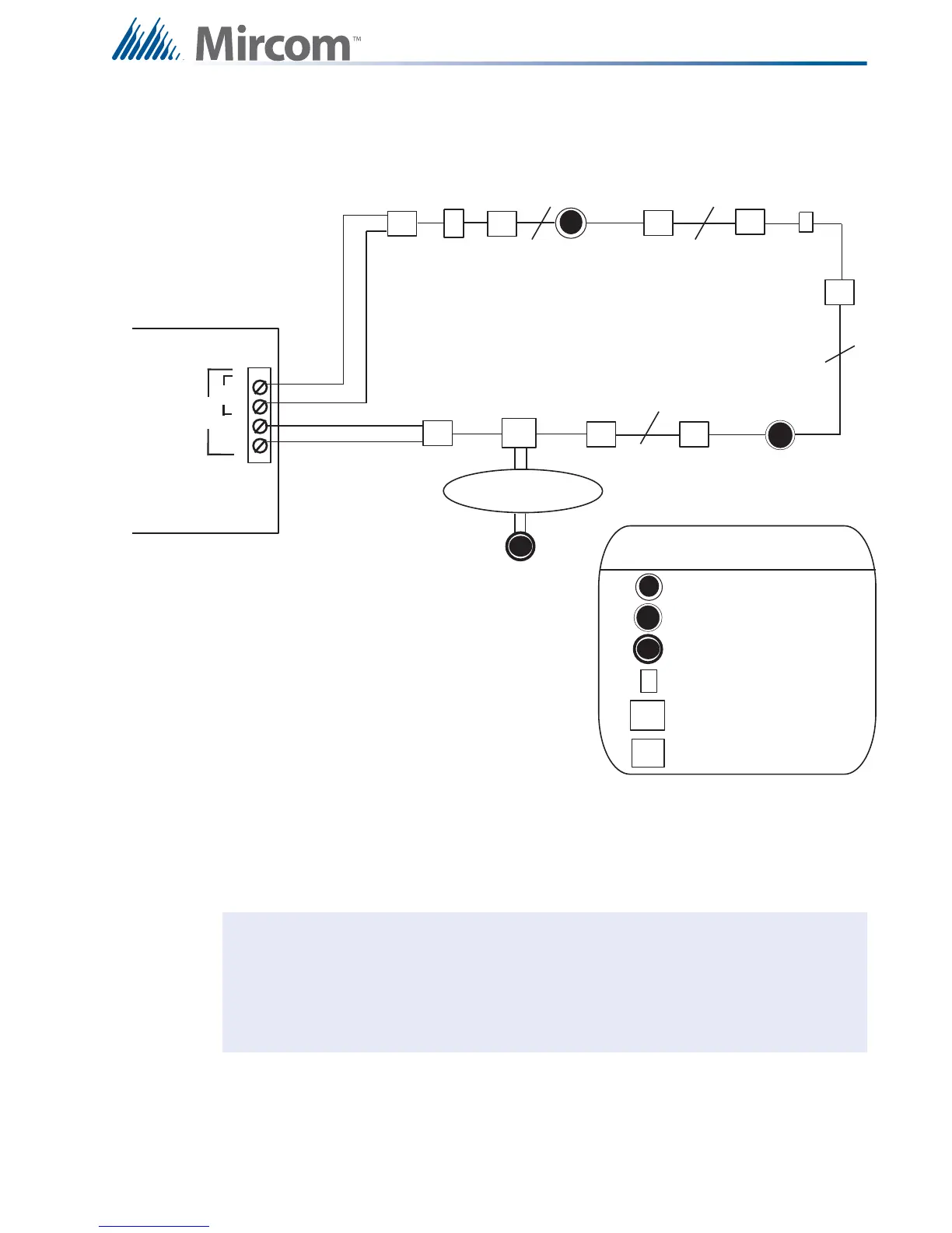
8.2.5 Single Loop Terminal Connections - Style 7
Figure 37 Single Loop Terminal Connections - Style 7
Notes: All power limited circuits must use type FPL, FPLR, or FPLP power limited cable.
Isolators need to be close nipple connected to the device being protected.
Loop wiring: maximum loop resistance is 40 ohms total. These lines are fully
supervised.
LEGEND
Ad d r essab l e Smo ke
Sensor with Isolator Base
Addressable Thermal
Sensor with Isolator Base
Conventional Smoke Sensor
Addressable Manual Pull Station
Fault Isolator Module
Conventional Heat Sensors
and Manual Pul l St at ions
F
C
s
F
ADDRESSABLE
THERMAL SENSOR
WITH ISOLATOR
BASE
ADDRESSABLE
SMOKE DETECTOR
WITH ISOLATOR
BASE
F
C
s
Addressable Monitor Module
H
S
S
H
TWO WIRES
TWO WIRES
TWO WIRES
TWO WIRES
I
I
I
I
I
I
I
I
M
M
I
B
A
ANALOG
LOOP A
+
-
+
-
ALC-198S SINGLE
LOOP MODULE
STYLE 7: For Style 7 operation use isolator
bases for the detectors and use isolator modules
(front and back as shown in this diagram) for the
addressable pull stations, monitor modules, and
control modules