4
2.2 Switch On
Press the On/Off [
] button until all the display
pixels are turned on and an audible signal is
heard. The meter performs a self-test function:
All the display pixels are turned on
The buzzer is activated
The vibration is activated
The display backlight is switched on
The battery condition is tested
The HV-generator is tested
The presence of the RF link is checked and the connection is
established.
In case the internal Real Time Clock (RTC) is not set to the proper
time, a flashing ‘TIME NOT SET’ message is displayed. The RTC can
be set with the CSW-31 software.
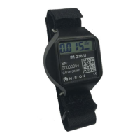
2.3 Switch Off (OFF)
To switch the instrument off:
Activate the menu (Short [Ξ]).
The display changes to blinking OFF.
Press an intermediate [
]
The display goes blank. The instrument is now switched off.
Note: The instrument does not completely shut down all the internal
circuitry. The RTC-circuit remains active maintaining the time signal. The
energy is supplied with the batteries. This means that the time setting of
the instrument RTC is lost in case the batteries are removed for more than
1 minute.
Note: In case the instrument is to be stored for a prolonged period of time,
it is advisable to remove the batteries to prevent any electrolyte leakage to
the battery compartment.
3 Main Parts of the RDS-31
This paragraph presents the main parts of the instrument.
3.1 Display of the RDS-31
The display of the RDS-31 is a 128 x 64
pixel graphical display with the Energy
Saving Backlight (ESB). The ESB-circuitry
measures the ambient light condition and in case the lighting is
sufficient, the backlight is not activated when the buttons are
operated.
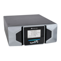
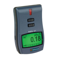
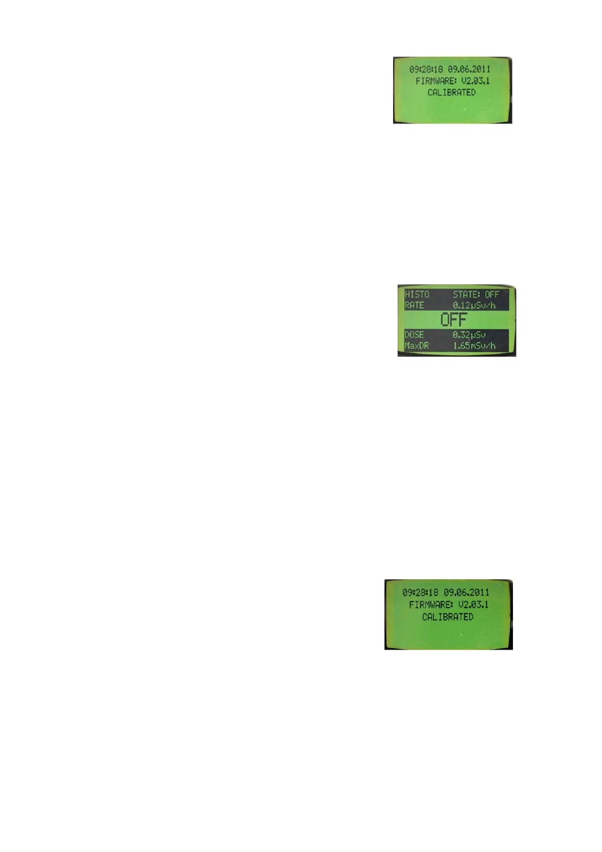
The start-up display informs current date & time, FW version
and calibration state. In case the time of meter’s Real Time
Clock is not set, the flashing ‘TIME NOT SET’ message is seen on
the 1
st
row. The RTC can be set with the CSW-31 software.
 Loading...