149
LCD PC E
LCD PC E
-
-
8590 MAINTENANCE
8590 MAINTENANCE
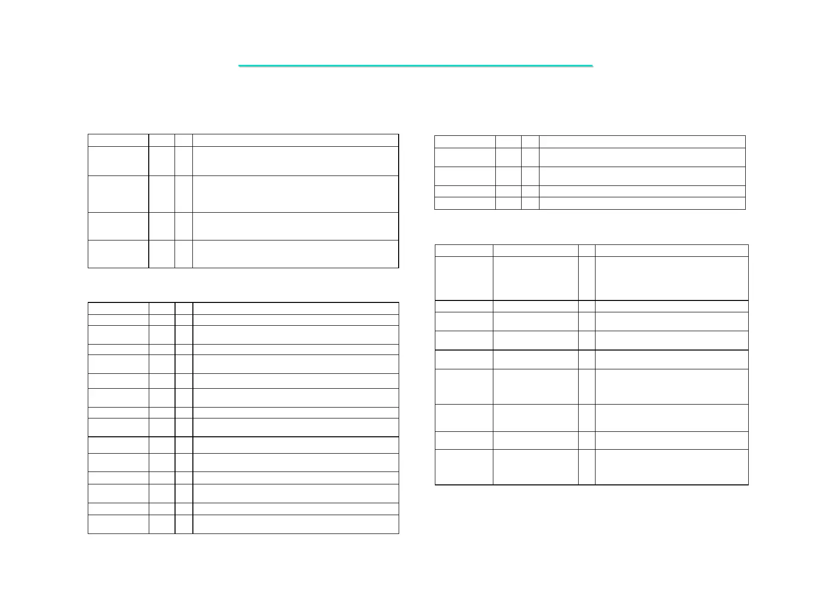
Reference Voltages
Signal Name Pin # I/O
Signal Description
HCMPVREF
G24
P
Host CPU Compensation Voltage Reference. 1/3 VTT ±2%
typically derived using a resistive voltage divider. See
P4N266A Design Guide.
MEMVREF
AD7,
AD12,
AD18,
AD23
P
Memory Voltage Reference. 1/2 VCC25 ±2% typically
derived using a resistive voltage divider. See P4N266A Design
Guide.
VLVREF
Y5
P
V-Link Voltage Reference.
0.9V derived using a resistive
voltage divider consisting of 2K . 1% to VCC25 and 1.13K .
1% to ground.
AGPVREF
G6, R6
P
AGP Voltage Reference.
0.4 VCCQQ (1.32V) when VCCQQ
is 3.3V and 0.5 VCCQQ (0.75V) when VCCQQ is 1.5V. Check
the VT8703A Design Guide for additional information.
Compensation
Signal Name Pin # I/O Signal Description
HRCOMP
F25
AI
Host CPU Compensation. Connect 20.5. 1% resistor to
ground. Used for Host CPU interface I/O buffer calibration.
VLCOMP
AB4
AI
Vlink P-Channel Compensation.
Connect 70. 1% resistor to
ground.
GCOMPN0
A2 AI
AGP N-Channel Compensation 0.
GCOMPN1
B3 AI
AGP N-Channel Compensation 1.
Analog Power / Ground
Signal Name Pin # I/O Signal Description
VCCHCK
N24 P
Power for Host CPU Clock PLL (2.5V ±5%)
GNDHCK
M24
P
Ground for Host CPU Clock Circuitry. Connect to main
ground plane through ferrite bead.
VCCMCK
AD24 P
Power for Memory Clock PLL
(2.5V ±5%)
GNDMCK
AC24 P Ground for Memory Clock Circuitry. Connect to main
ground plane through ferrite bead.
VCCMDLL
AE15 P
Power for Memory Strobe DLL
(2.5V ±5%)
GNDMDLL
AD15
P
Ground for Memory Strobe DLL Circuitry.
Connect to main
ground plane through ferrite bead.
VCCRGB
E6 P
Power for CRT RGB Outputs (2.5V ±5%).
GNDRGB
C5
P
Connection Point for RGB Load Resistors. Connect to main
ground plane.
VCCDAC
C6 P
Power for DAC Digital Logic.
(2.5V ±5%)
GNDDAC
D6
P
P
Ground for DAC Analog Circuitry.
Connect to main
ground plane through a ferrite bead.
VCCPLL1
C7 P
Power for PLL1 (2.5V ±5%).
GNDPLL1
B7
P
Ground for PLL1. Connect to main ground plane through a
ferrite bead.
VCCPLL2
E7 P
Power for PLL2
(2.5V ±5%).
GNDPLL2
D7
P
PGround for PLL2. Connect to main ground plane through a
ferrite bead.
Digital Power / Ground
Signal Name Pin # I/O Signal Description
VTT
E16,23,
F17-18,23,K14-20,24,
L20,M20, N20, P20, R20,
T20,24,U20,24, Y25,
AA24, AB24
P
Power for CPU I/O Interface Logic (25Pins).
The voltage is CPU dependent. The VT8703A
can support both desktop and mobile P4 CPUs.
These two types of CPUs have different working
voltages (see CPU specs for more information).
GNDTT
E19, P24 P Ground for CPU I/O Interface Logic (2 Pins).
VCCMEM
V20, W10,20, Y10-20,
AA9-20
P
Power for Memory I/O Interface Logic (26
Pins). 2.5 ±5%.
VCCVL
U9-10, V9-10, W9, Y9
P
Power for V-Link I/O Interface Logic (6 Pins).
2.5V
±
5%
VCCFP
K11-13
P
Power for Flat Panel I/O Interface Logic (3
Pins).
3.3V
±
5%
VCCAGP
K6,9, L6,9-10, M6,9-10,
N9-10, P9-10, R9-10,
T6,9-10, U6, V6
P
Power for AGP Bus I/O Interface Logic (19
Pins). 1.5 / 3.3V±5% (Device 0 RxB2[1] should
be set to indicate the voltage).
VCCQQ
A4
P
AGP Quiet Power. Connect to main AGP power
(VCCAGP =1.5 / 3.3V
±
5%) through a ferrite
bead.
GNDQQ
A3
P
Ground for AGP Quiet Power. Connect to
main ground plane.
VCC25
F9-11,14-15,20-21, H6,24,
J6,24,N6, P6, W6,24,
Y6,24, AA6,
AD9-11,13-14,20-22
P
Power for Internal Logic (26 Pins). 2.5V ±5%
5.2 VIA VT8703 North Bridge with S3 Savage4 AGPX4