21/1531-ASP11301 Uen B3 2016-02-17 14
C
ABLING
*) Fan BFD50908
Note: Consider the needed cabling for network or server redundancy. For more infor-
mation, see the description for MIVOICE MX-ONE, chapter REDUNDANCY.
3.1 CONNECTOR POSITIONS
Only boards with EMC shielded fronts are used in the MX-ONE subracks.
3.1.1 CONNECTOR NUMBERING
The connector positions are marked in numerical order starting from 1 for the lowest
connector position, 2 for the position above it and so on, see Figure 9: Connectors
positioning on page 15.
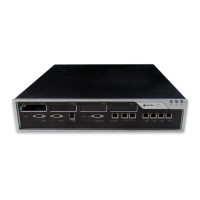
MX-ONE 1U
chassis,
87L00032xAA-A
TSR9020279/2000 to AC/DC, 48V
Network TSR 482 0211/20M LAN, 100KBit. RJ45 - RJ45, straight. L=20
meters
61L00002BAA-A LAN, 1GBit, RJ45 - RJ45, straight.
L= 20 meters
Power to Fan*) TSR 903 021/5000, /12M,
TSR 490 0116/5000, /12M for UK
to AC/DC, 48V
Fan *) to alarm TSR 902 0274/2200
TSR 902 0277/2000
SXK 106 2097/1
Alarm cables and plug
Unit Cable Product Number Remarks