21/1531-ASP11301 Uen B3 2016-02-17 48
A
LARMS
To connect the alarm cable on the rear side of the chassis, a break-out plate has to be
removed. Open the top cover and break out the plate. Use a plier and fold back and
forth until it breaks of.
For details about the 1U-power connection, see doc. BCG 00031.44, Supplier User
Manual.
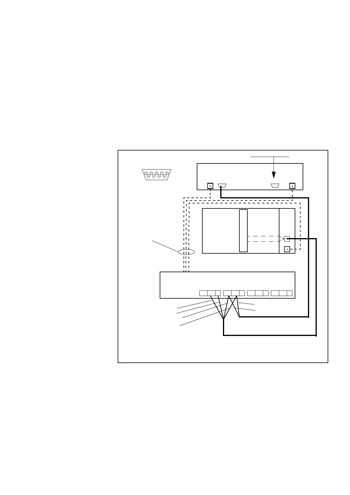
5.4.2 MIVOICE MX-ONE CLASSIC WITH 2U POWER UNIT
Alarms from FAN_2 units and alarms from power supply can be routed to the MX-ONE
system via the ALARM inlet on either the DC/DC board if a MX-ONE Classic (7U-unit)
is used or in the front/back of a MX-ONE Lite (3U-unit) is used.
The Supervision Extension port must be terminated with alarm plug SXK 106 2097/1
on the FAN_2 unit.
Figure 39: MGU Power and Fan alarm in Classic subracks
The following connections are used:
1. Power cable TSR 903 021/5000 (free end on power unit side)
2. * Alarm cable TSR 902 0277/2000 (free end on power unit side)
3. * FAN_2 Alarm cable TSR 902 0274/2200 (free end on power unit side)
4. * Alarm plug SXK 106 2097/1
MX-ONE FAN_2
MX-ONE
DC/DC
Rear side of 2U AC/DC
NC NO C
Relay 4
NC NO C
Relay 3
NC NO C
Relay 2
NC NO C
Relay 1
Alarm
-48V
Blue
-48VDC -48VDC
4*) Alarm Plug
Supervision ExtensionSupervision
1*)
2*)
3*)
White
Supervision
1 2345
6 789
Pin 9 Alarm relay
Alarm A
Alarm B
MGU
Pin 5 GND
Classic
Turquoise
Violet
Violet
Turquoise
White, relay, Alarm A
Blue, GND
Violet, relay, Alarm B
Turquoise, GND