INSTALLING BOARDS AND CABLING
31 21/1531-ASP11301 Uen B3 2016-02-17
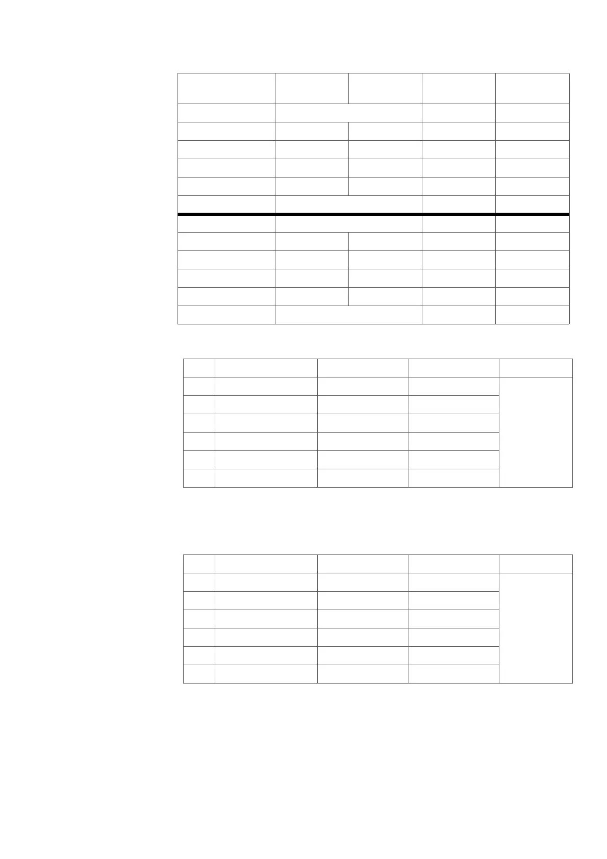
Table 10 Synchronization ring front connector TX configuration. (X13)
Note: If the Sync cable is prolonged, the Twisted pair configuration and polarity has to
be kept. See Figure 22: Sync ring cable design (TSR9011226) on page 32
Table 11 Synchronization ring front connector RX configuration. (X12)
Note: If the Sync cable is prolonged, the Twisted pair configuration and polarity has to
be kept. See Figure 22: Sync ring cable design (TSR9011226) on page 32
7 Not used EPB3 (brown) EPA3 (white)
8 EPB1 (white) EPA1 (orange) EPB2 (green) EPA2 (white)
9 LB15 (yellow) LA15 (brown) EPB0 (blue) EPA0 (white)
10 LB13 (yellow) LA13 (orange) LB14 (green) LA14 (yellow)
11 LB11 (black) LA11 (brown) LB12 (blue) LA12 (yellow)
12 Not used LB10 (green) LA10 (black)
13 Not used LB9 (orange) LA9 (black)
14 LB7 (red) LA7 (brown) LB8 (blue) LA8 (black)
15 LB5 (red) LA5 (orange) LB6 (green) LA6 (red)
16 LB3 (white) LA3 (brown) LB4 (blue) LA4 (red)
17 LB1 (white) LA1 (orange) LB2 (green) LA2 (white)
18 Not used LB0 (blue) LA0 (white)
ABCD
1 Ring TX comm+ Bus comm+ Bus 0 Volt Not used
2 ACDM RX+ Not used ACDM TX+
3 Ring TX comm- Buss comm- Bus TX-strap
4 ACDM RX- Not used ACDM TX-
5 Ring TX sync+ Bus sync+ Ring 0 Volt
6 Ring TX sync- Bus sync- Ring TX-strap
ABCD
1 Ring RX comm- Bus comm+ Bus RX-strap Not used
2 ACDM TX+ Not used ACDM RX+
3 Ring RX comm+ Buss comm- Bus o Volt
4 ACDM TX- Not used ACDM RX-
5 Ring RX sync+ Bus sync+ Ring RX-STRAP
6 Ring RX sync- Bus sync- Ring 0 Volt
Connector row
ABCD