M800W/M80W Series Connection and Setup Manual
2 General Connection Diagram
7
IB-1501268-K
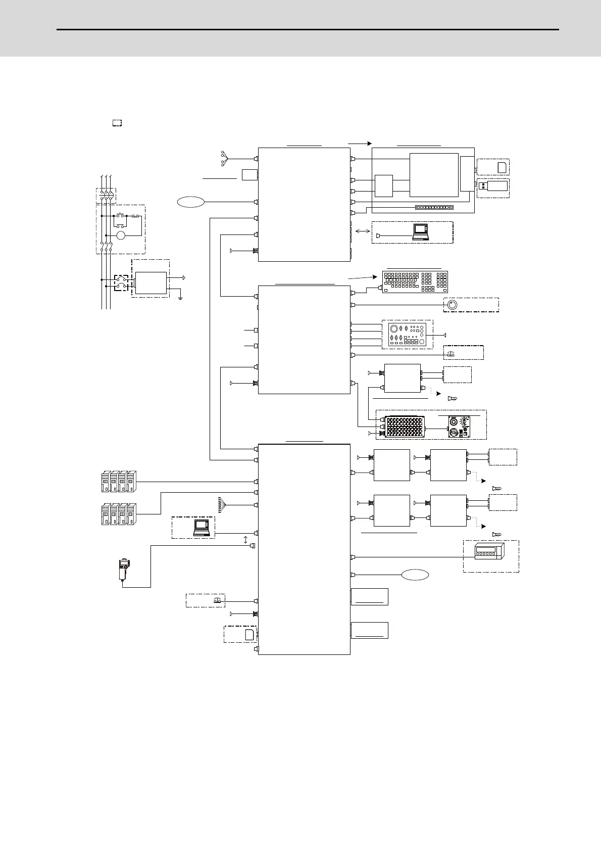
2.2 General Connection Diagram [M80W]
2.2.1 M80W, Windows-based Display (15-type)
(Note 1) For information on how to connect the drive unit, refer to the drive unit's manual.
(Note 2) For the connection of machine operation panel, refer to the chapter "Connection of Machine Operation Panel".
(Note 3) When using a keyboard unit, install the operation panel I/O unit on the back of the keyboard unit.
(Note 4) When the handle of handy terminal is used, connect ENC connector of G430 cable to MPG connector of the
operation panel I/O unit.
Because the pin assignment of ENC connector of G430 is different from that of MPG connector of the
operation panel I/O unit, conversion is required.
The conversion cable needs to be prepared by the MTB.
SIO
1ch:J030
2ch:J031
2ch
RS232C
SKIP
RIO2
SD
RIO3
GDI
LAN
J303
Network
FCU8-EX56x
J100
SD
FCU8-DX2xx/DX6xx/DX4xx
RIO1
DCIN
J070/071
(EcoMonitor)
OPTH1
OPTH2
J395/J396
J395/J396
EMG
J120
Max. 8 points
J070/071
J070/071
J210
DI:CJ31/33
DO:CJ32/34
RIO1
DCIN
RIO2
DI:CJ31/33
DO:CJ32/34
RIO1
DCIN
RIO2
J350/351
J350/351
J070/071
J070/071
J210
DI:CJ31/33
DO:CJ32/34
RIO1
DCIN
RIO2
DI:CJ31/33
DO:CJ32/34
RIO1
DCIN
RIO2
J350/351
J350/351
(R2-TM)
(R2-TM)
FG
5V:J023/J024/J025
12V:J020/J021/J022
L1 L2
L3
(NFB)
DCOUT
FG
ACIN
CP
MC
ON OFF
MC
MC
J350/351
J350/351
J350/351
J350/351
FCU8-EX54x
EXT1
EXT3
G430
device
Skip signal input
Communication
expansion unit
Control unit
Max. 32 units for each port
Remote I/O unit
Remote I/O unit
Remote I/O unit
Remote I/O unit
24VDC
Energy measuring units
Drive units
Stored in control unit
To the next
remote I/O or
terminator
connector
To the next
remote I/O or
terminator
connector
Emergency
stop switch
SD
memory
card
24VDC24VDC
24VDC24VDC
Machine
control
relay/contact
Machine
control
relay/contact
24VDC
Manual pulse
generator (5V/12V)
Machine operation panel
made by the machine tool builder
Dotted lines indicate the sections prepared by the machine tool builder.
<> Angle brackets indicates attached cable of unit.
No-fuse breaker
24VDC stabilized
power supply
Function
expansion unit
(Note 1)
Handy terminal
FCU8-MU044
RIO4/M
BTBOX
J120
ON/OFF
CFAST
CFast
LVDS1
USB2-1
USB2-2
FCU8-PC231
LAN
J303
MENUKEY
RIO3EXT
ON
OFF
G170
MPG
INV
RS232C
USB-RS232C
GDI
KEYUSB
RIO3
J303
NCKB
KEYUSB
J210
J291
J210
LVDS2
SD
DCIN
J070/071
EMG
USB
USB3-2
USB3-1
USB2-4
USB2-3
USB2-6
USB2-5
FCU8-DX2xx/DX6xx/DX4xx
CJ71
FCU8-CF001-001
DCIN
J070/071
Network
CG31
CG32
FCU8-DX830/834/837
CG33
CG34
SDI
Max. 8 points
DI:CJ31/33
DO:CJ32/34
RIO1
DCIN
RIO2
J350/351
J350/351
(R2-TM)
J210
FCU8-KB92x
FCU8-KB941/KB931
<G460>
DX834:
DX837:
OPKB
J460/461
24VDC
Machine operation panel (Note 2)
Emergency
stop switch
Personal computer unit
device
conversion
24VDC
USB memory
24VDC
Remote I/O unit
24VDC
Operation panel I/O unit
Safety signal input
Stored in
personal computer unit
CFast unit
(Safety signal input is
DX837 only.)
To the next remote I/O
or terminator connector
Added onto back of
display unit
SD
memory
card
24VDC
Machine
control
relay/contact
Backlight
I/F PCB
With scan input/output
With safety signal input
Scan input /
Scan output
(Scan input/output is
DX834 only.)
FCU8-KB04x/KB083
<G402>
<J09x>
USB
SD
<J292>
<J190>
<J290>
<J081>
<J420>
Keyboard unit
(Note 3)
15-type LCD
with touch panel
Display unit
Menukey
FCU8-DU181-36
 Loading...