Connection Safety circuits
SD-/SQ series 4 - 11
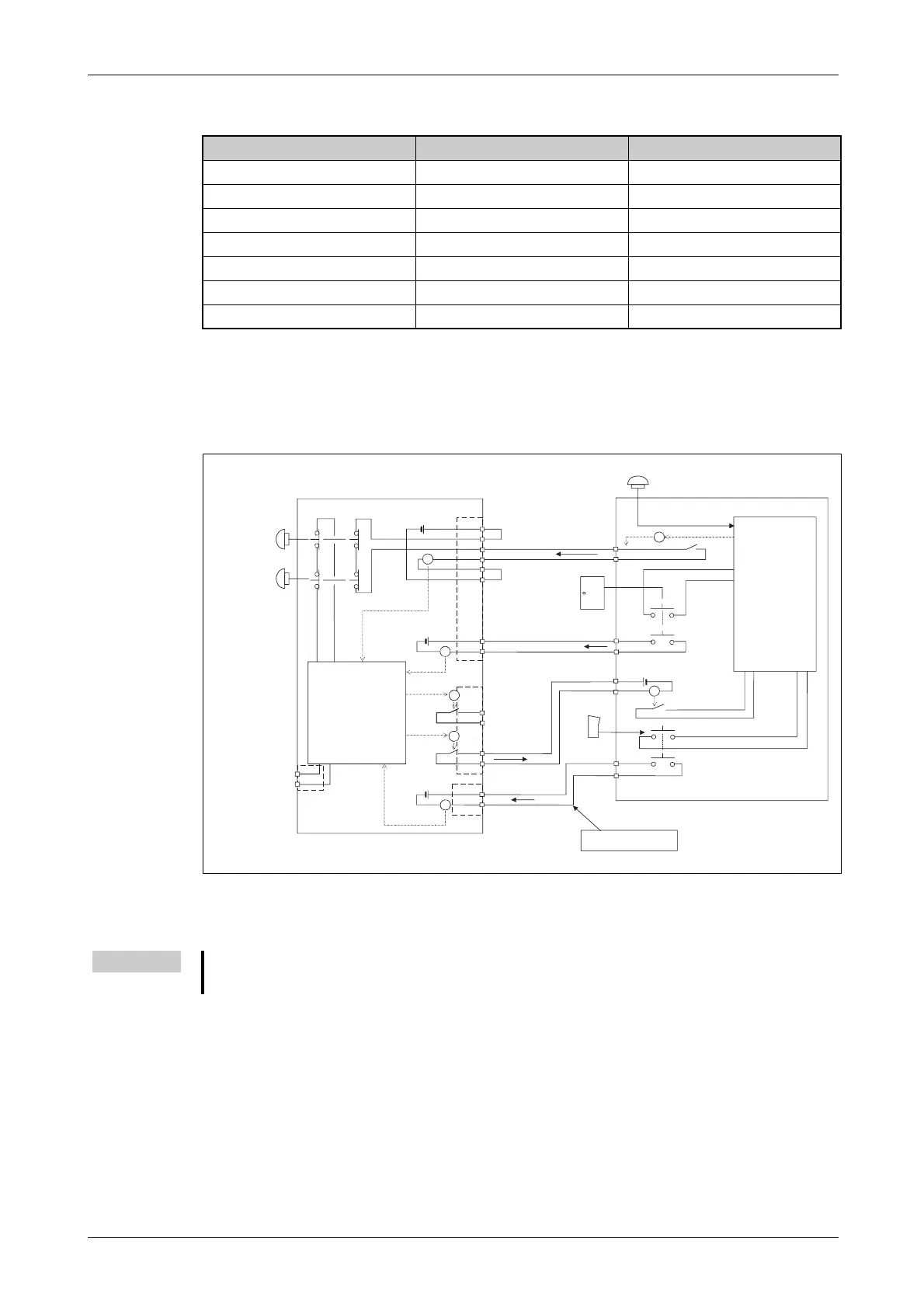
Example 2
The following figure presents an example of the configuration of a safety circuit using the output to
output the operating mode.
EMERGENCY-STOP input I/O connected
External EMERGENCY-STOP switch I ✔
Door contact I ✔
Enable switch input
I ✔
Error output O —
Auxiliary axis output O —
Operating mode output O —
External relay connection — ✔
Tab. 4-1:
Inputs and outputs
R001515E
Fig. 4-12:
Configuration of a safety circuit (Example 2)
NOTE
To facilitate clarity, some information has been omitted from the figure; the figure therefore devi-
ates from the actual conditions of the product.
1A/1B
2A/2B
3A/3B
4A/4B
5A/5B
6A/6B
8A/8B
9A/9B
1A/1B
2A/2B
3A/3B
4A/4B
10A/10B
11A/11B
5A/5B
6A/6B
EMGIN1/2
EMGIN1/2
EMGOUT1/2
EMGOUT1/2
}
RA
RA
RA
RA
RA
RA
RA
Control unit 1
EMERGENCY-STOP
control unit
EMERGENCY-STOP
Teaching Box
Internal
safety
circuit
Control output
Auxiliary axes
Input
door contact
Error output
including
SW EMERGENCY-STOP
Output for
operating mode Enable
switch
External EMERGENCY-
STOP input
Enable
switch input
Bridge
Peripheral units
Internal
safety
circuit
Door
Output for system
EMERGENCY-STOP
(to be provided by
the user)
Output for
door contact
Enable switch
Teaching Box release
switch
 Loading...


