E-10
3 Wiring
FX
3S
/FX
3G
/FX
3GC
/FX
3U
/FX
3UC
PLC User's Manual - Analog Control Edition
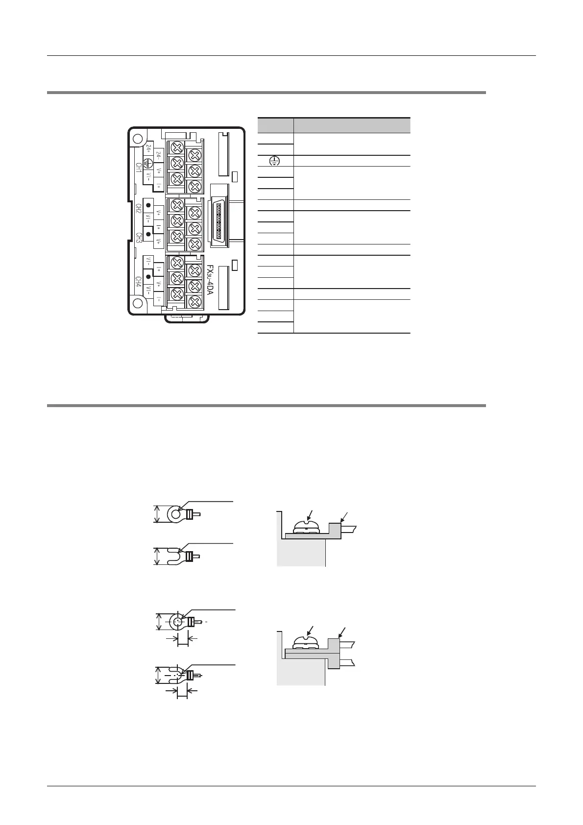
FX3U-4DA (4-channel Analog Output)
3.1 Terminal Layout
3.1 Terminal Layout
The terminals of FX3U-4DA are arranged as follows:
3.2 Cable and Terminal Tightening Torque
The FX3U-4DA terminal block is designed for M3 screws.
The end disposal of the cable shown below.
Tighten the terminal to a torque of 0.5 to 0.8 N•m.
Do not tighten terminal screws with a torque outside the above-mentioned range.
Failure to do so may cause equipment failures or malfunctions.
• When one wire is connected to one terminal
• When two wires are connected to one terminal
24+
24-
VI-
I+
V+
VI-
V+
VI-
V+
V+
VI-
I+
I+
I+
Signal
Application
Ground terminal
24 V DC power supply
Channel-1 analog output
Channel-2 analog output
Channel-4 analog output
Channel-3 analog output
Do not connect any lines.
Do not connect any lines.
Do not connect any lines.
φ3.2 (0.13")
6.2 mm (0.24")
or less
Terminal
screw
Crimp
terminal
Terminal
6.2 mm (0.24")
or less
φ3.2 (0.13")
6.3 mm (0.25")
or more
6.3 mm (0.25")
or more
Terminal
screw
Crimp
terminal
Terminal
6.2 mm (0.24")
or less
6.2 mm (0.24")
or less
3.2 (0.13")
3.2 (0.13")
 Loading...


