E-11
3 Wiring
A
Common Items
B
FX
3U
-4AD
FX
3UC
-4AD
C
FX
3U
-4AD-ADP
D
FX
3G
-2AD-BD
E
FX
3U
-4DA
F
FX
3U
-4DA-ADP
G
FX
3G
-1DA-BD
H
FX
3U
-3A-ADP
I
FX
3U
-4AD-PT
-ADP
J
FX
3U
-4AD-PTW
-ADP
FX
3S
/FX
3G
/FX
3GC
/FX
3U
/FX
3UC
PLC User's Manual - Analog Control Edition
FX3U-4DA (4-channel Analog Output)
3.3 Wiring to Power Supply Terminals
3.3 Wiring to Power Supply Terminals
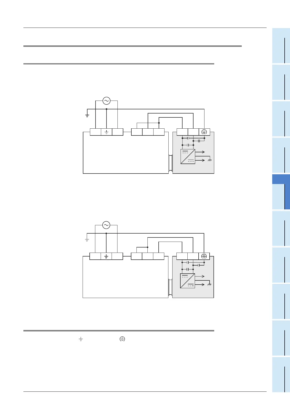
3.3.1 Examples of Power Supply Circuit
Below are examples of circuits for using the 24 V DC service power supply of the FX3G/FX3U Series PLC.
1) Sink input [- common] wiring
2) Source input [+ common] wiring
3.3.2 Cautions regarding wiring to the power supply terminals
• Ground the " " terminal and " " terminal to the Class - D grounding line (100 Ω or less) together
with the ground terminal of the main unit.
• For the timing of power-on/off when using an external power supply, see the following manual of the
connected PLC.
→ Refer to the FX
3G Series User's Manual - Hardware Edition.
→ Refer to the FX
3GC Series User's Manual - Hardware Edition.
→ Refer to the FX
3U Series User's Manual - Hardware Edition.
→ Refer to the FX
3UC Series User's Manual - Hardware Edition.
Class-D
grounding
L N
FX
3G
/FX
3U
Series PLC
(main unit)
24+ 24-S/S 0V 24V
+15V
-15V
FX
3U-4DA
AC power
100 to 240 V
Connect the "S/S" terminal of the main unit to the "24V" terminal.
Class-D
grounding
L N 24+ 24-S/S 0V 24V
+15V
-15V
FX
3U-4DA
AC power
100 to 240 V
Connect the "S/S" terminal of the main unit to the "0V" terminal.
FX
3G/FX3U Series PLC
(main unit)
 Loading...


