76/83
7.2 Connecting GOT and inverter via PLC (CC-Link IE Field Network)
This sample screen can also be used for connecting GOT2000 and MELSEC iQ-R/Q/L series PLC via Ethernet and
then connecting the PLC and the inverter via CC-Link IE Field Network master/local module. *1
The settings example for connection via MELSEC iQ-R CPU and CC-Link IE Field Network master/local module is
as below.
*1: Connection via CC-Link IE Field Network limits operation command and operation of machine diagnosis
(load characteristics measurement). For details, please refer to “7.2.8 precautions”.
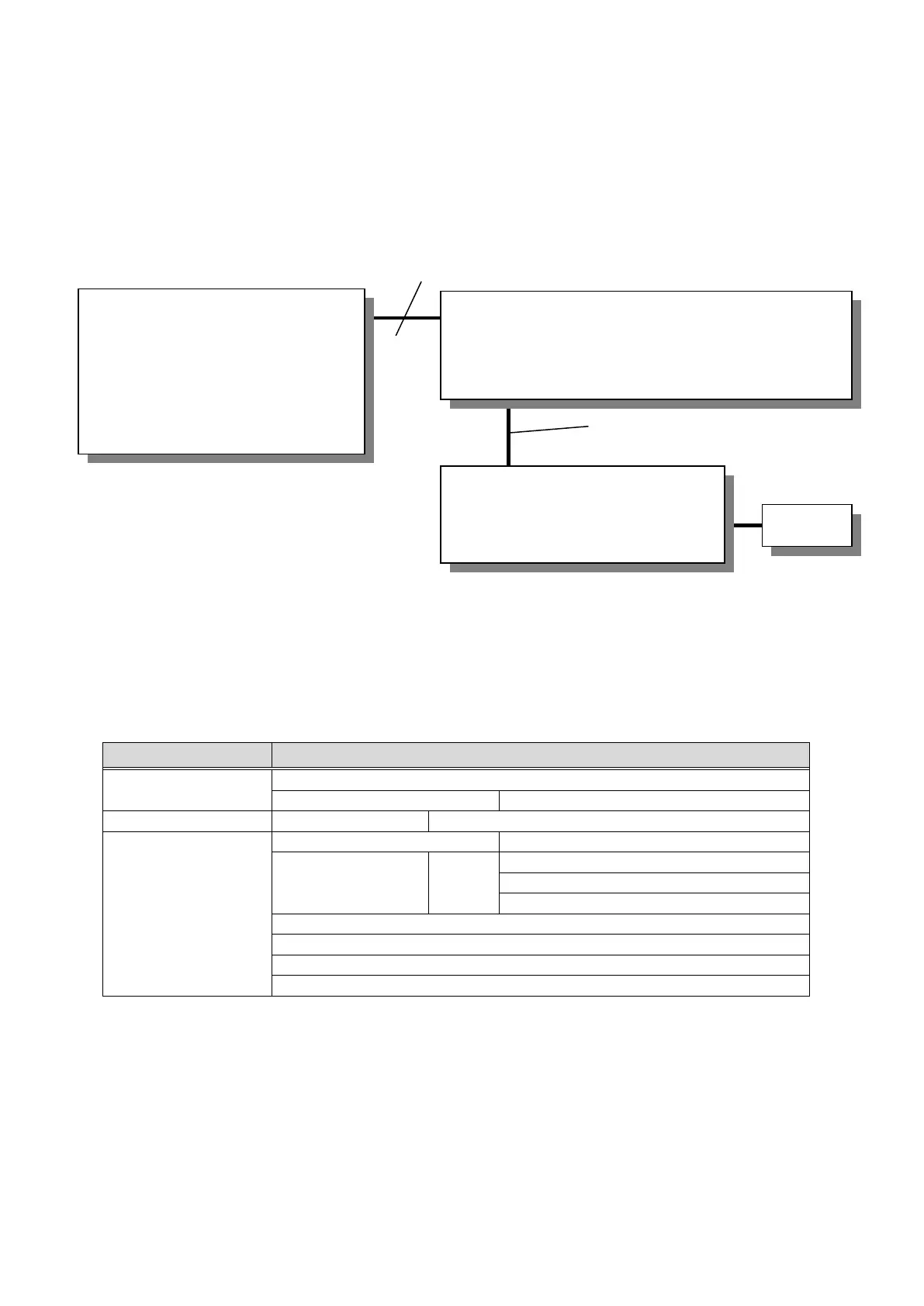
7.2.1 System Configuration
*1: The SD card is used for the recipe function and document display function.
*2: The battery is used to backup the clock data and the recipe data in the SRAM user area in case of power
failures. (The battery is included as standard in the GOT.)
*3: For more details on the cable, please refer to “15.3.1 Connection to FREQROL-A800/F800” in "GOT2000
Series Connection Manual (Mitsubishi Products)".
7.2.2 GOT
7.2.2.1 System Applications that are Automatically Selected
Model: Select MELSEC iQ-R, RnMT/NC/RT, CR800-D*1
Standard System Application
Ethernet(Mitsubishi Electric), Gateway
Key Window Design Information
Recipe Display (Record List)
*1: Change the models according to the CPU in use.
QCPU: MELSEC-Q/QS, Q17nD/M/NC/DR, CRnD-700
LCPU : MELSEC-L
GOT2000
・ GT27**-V(640×480)
・ Interface:
Standard I/F(Ethernet)
・ SD card*1
・ Battery (GT11-50BAT)*2
(Network No.1, Station No. 18,
IP: 192.168.3.18)
・MELSEC PLC(RCPU/QCPU/LCPU)
(Network No.1, Station No. 1, IP: 192.168.3.39)
+
・CC-Link IE Field Module
(Network No.2, Master Station)
・FR-A820-0.4K-GF
・Interface
: CC-Link IE Field
(Network No.2, Station No.1)

 Loading...


