E-12
FX Series PLC User's Manual - Data Communication Edition
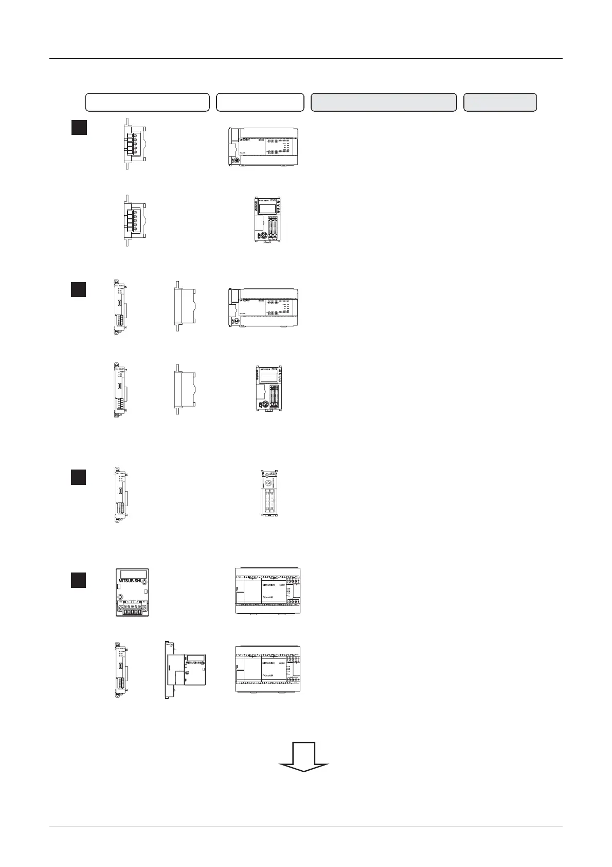
Inverter Communication
3 System Configuration and Selection
3.1 System Configuration
For communication equipment combinations for each FX Series, refer to the next section.
5
+
FX
3U
PLC
+
4
+
FX
3U
PLC
Communication equipment operating
in accordance with RS-485
FX PLC Important point in selection
Total extension
distance
Becouse the communication board
can be built in to the PLC, the
installation area does not change
50 m
(164' 0")
Attach the expansion board to the
main unit, and then attach the
communication adapter to the left
side of the main unit.
500 m
(1640' 5")
50 m
(164' 0")
500 m
(1640' 5")
+
Communication board FX
3UC
-32MT-LT(-2)
RD
RDA
RDB
SDA
SDB
SG
SD
+
Expansion
board
FX
3UC
-32MT-LT(-2)
Communication
adapter
+
Expansion
board
Communication
adapter
Communication board
RD
RDA
RDB
SDA
SDB
SG
SD
6
7
FX
3UC
FX
3G
PLC
FX
3G
PLC
(D, DSS)
Communication
Communication
board
adapter
Communication Connector
conversion
adapter
adapter
Attach the communicaion adapter to
Attach the connector conversion adapter
to the main unit, and then attach the
communication adapter to the left side
of the main unit.
Because the communication
board can be built in to the PLC,
the installation area does not
change.
the left side of the main unit.
500 m
(1640' 5")
+
+
++
 Loading...


