A-5
FX Series PLC User's Manual - Data Communication Edition
Common Items
1 Introduction
1.2 Outline and Features of Communication Types
A
Common Items
B
N:N Network
C
Parallel Link
D
Computer Link
E
Inverter
Communication
F
Non-Protocol
Communication
(RS/RS2 Instruction)
G
Non-Protocol
Communication
(FX
2N
-232IF)
H
Programming
Communication
I
Remote
Maintenance
Apx.
Discontinued
models
1.2.2 N:N Network
→ Refer to the "N:N Network" section.
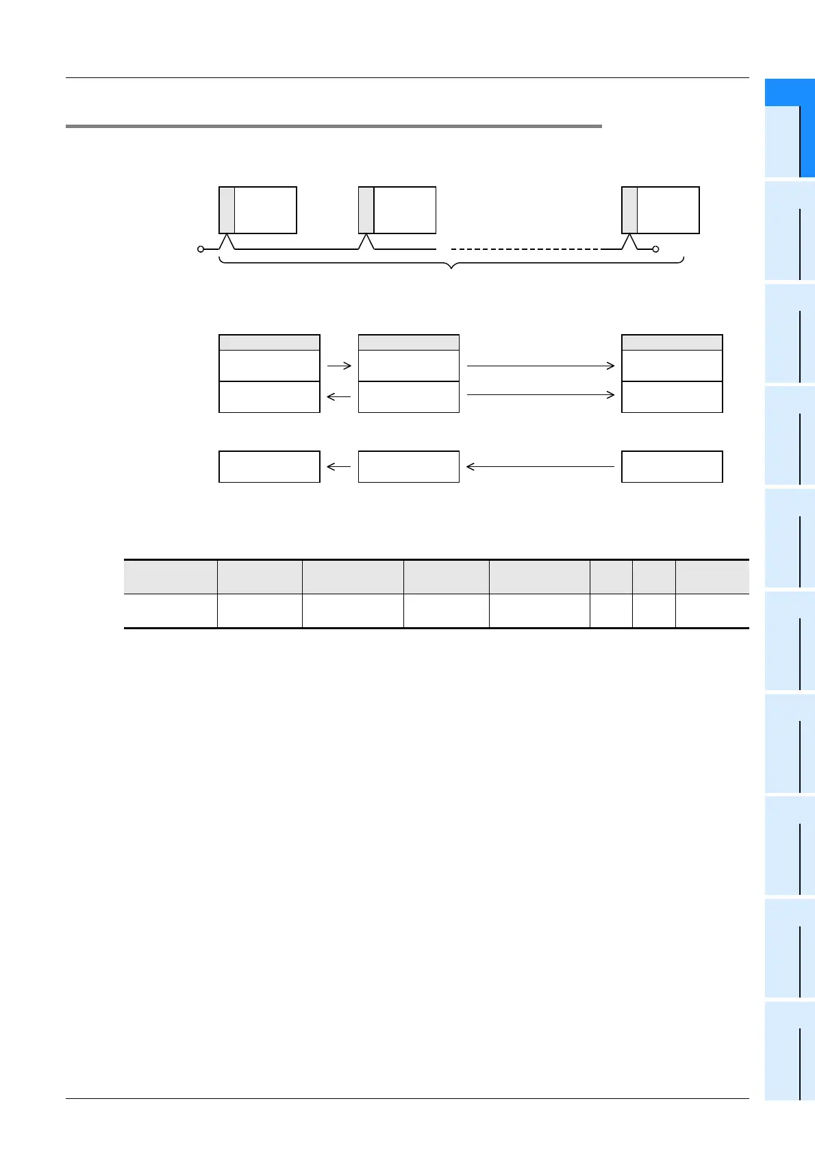
1. Outline
2. Applicable PLCs
:Applicable (If applicable versions of main units are limited, they are described inside ( ).)
—:Not applicable
3. Communication targets
Between FX1S, FX0N, FX1N, FX2N, FX3G, FX3U, FX1NC, FX2NC, and FX3UC Series PLCs
4. Function
This network allows up to eight connected FX PLCs to automatically transfer data among the connected
PLCs.
In the network, data can be transferred among PLCs for devices determined in the refresh range, and those
devices can be monitored by every PLC.
5. Applications
By this network, data link can be achieved in a small-scale system, and the machine information can be
transferred between machines.
PLC FX2(FX),FX2C FX0N
FX1S,FX1N,
FX
1NC
FX2N FX2NC FX3G FX3U,FX3UC
Communication
applicability
—
(Ver.2.00 or later)
(Ver.2.00 or later)
RS-485
FX CPU
Station
No. 0
RS-485
FX CPU
Station
No. 1
RS-485
FX CPU
Station
No. 7
. . . . . . . . . . .
•
Number of connectable FX PLCs : 8 maximum (station Nos. 0 to 7)
•
Total extension distance : 500 m (1640' 5") [50 m (164' 0") when 485BD is connected]
For FX
3U
PLC (pattern 2)
Station No. 0
M1000 to M1063
D0 to D7
M1064 to M1127
D10 to D17
M1448 to M1511
D70 to D77
Station No. 1
M1000 to M1063
D0 to D7
M1064 to M1127
D10 to D17
M1448 to M1511
D70 to D77
Station No. 7
M1000 to M1063
D0 to D7
M1064 to M1127
D10 to D17
M1448 to M1511
D70 to D77
Terminal
resistor
Terminal
resistor
. . .
. . .
. . .
 Loading...


