E-19
FX Series PLC User's Manual - Data Communication Edition
Inverter Communication
4 Wiring
4.2 Selecting Cables and Connection Devices
A
Common Items
B
N:N Network
C
Parallel Link
D
Computer Link
E
Inverter
Communication
F
Non-Protocol
Communication
(RS/RS2 Instruction)
G
Non-Protocol
Communication
(FX
2N
-232IF)
H
Programming
Communication
I
Remote
Maintenance
Apx.
Discontinued
models
4.2 Selecting Cables and Connection Devices
When connecting equipment operating in accordance with RS-485, use the following connection method with
10BASE-T or shielded twisted pair cables.
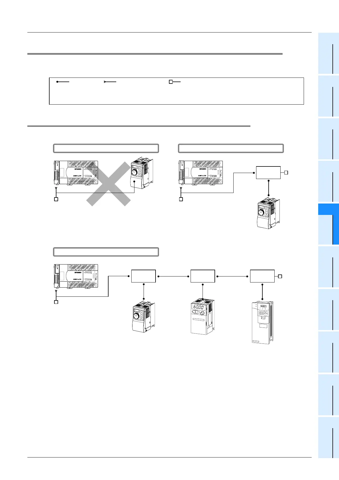
4.2.1 S500, E500, A500, F500, V500, D700 and E700 Series (PU connector)
1. In the case of 1-to-1 connection
2. In the case of 1-to-N connection
PU connector
(RJ45 connector)
Non-stranded cable
(10BASE-T cable for LAN)
Terminal resistor
(which is supplied with communication equipment for the
FX PLC side, and should be arranged by the user for the
inverter side)
10BASE-T cable
Terminal resistor
RS-485 connector
(PU connector)
When a distributor is not used
Use a distributor because a terminal resistor cannot
be connected to the inverter.
Distributor
RS-485 connector
(PU connector)
10BASE-T cable
Terminal
resistor
Terminal resistor
10BASE-T cable
When a distributor is used
RS-485 connector
10BASE-T cable
Terminal resistor
DistributorDistributor
10BASE-T cable
10BASE-T
cable
10BASE-T
cable
Distributor
Terminal
resistor
When a distributor is used
PU
connector
10BASE-T cable
PU
connector
10BASE-T cable
 Loading...


