E-25
FX Series PLC User's Manual - Data Communication Edition
Inverter Communication
4 Wiring
4.4 Connection Devices (RJ45 Connector and Distributor)
A
Common Items
B
N:N Network
C
Parallel Link
D
Computer Link
E
Inverter
Communication
F
Non-Protocol
Communication
(RS/RS2 Instruction)
G
Non-Protocol
Communication
(FX
2N
-232IF)
H
Programming
Communication
I
Remote
Maintenance
Apx.
Discontinued
models
2. Terminal block
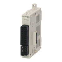
In the FX0N-485ADP, the terminal screw size is "M3".
Make sure to use a crimp-style terminal with the following sizes.
Make sure that the tightening torque is 0.5 to 0.8 N·m.
• When wiring one cable to one terminal
• When wiring two cables to one terminal
4.4 Connection Devices (RJ45 Connector and Distributor)
Prepare the following devices if necessary.
4.5 Connecting Terminal Resistors
Connect a terminal resistor to both the communication equipment of the FX PLC and the RDA-RDB signal
terminal in the last inverter.
→ For details on connection, refer to each wiring diagram.
1. Terminal resistor types
Prepare the following two types of terminal resistors.
Product name Model name Manufacturer Check
RJ45 connector 5-554720-3 Tyco Electronics AMP K.K.
Distributor
BMJ-8
Modular rosette
Do not use a plug with terminal resistor
supplied together with the modular rosette
above.
HACHIKO ELECTRIC CO., LTD
Terminal
Terminal
screw
Crimp-style
terminal
6.2 mm (0.24")
or less
φ
3.2 (0.13")
6.3 mm (0.25")
or more
6.2 mm (0.24")
or less
6.3 mm (0.25")
or more
φ
3.2 (0.13")
6.2 mm (0.24")
or less
φ
3.2 (0.13")
6.3 mm (0.25")
or more
6.2 mm (0.24")
or less
6.3 mm (0.25")
or more
φ
3.2 (0.13")
Terminal
Terminal
screw
Crimp-style
terminal
1 1 1 =110
Ω
Brown
(10
1
)
Precision
1 0 1 =100
Ω
(10
1
)
Black PrecisionBrownBrown

 Loading...


