E-95
FX Series PLC User's Manual - Data Communication Edition
Inverter Communication
9 Creating Programs (for FX3G, FX3U and FX3UC PLCs)
9.8 Inverter Parameter Batch Writing (PLC
→
Inverter) [FNC274 / IVBWR]
A
Common Items
B
N:N Network
C
Parallel Link
D
Computer Link
E
Inverter
Communication
F
Non-Protocol
Communication
(RS/RS2 Instruction)
G
Non-Protocol
Communication
(FX
2N
-232IF)
H
Programming
Communication
I
Remote
Maintenance
Apx.
Discontinued
models
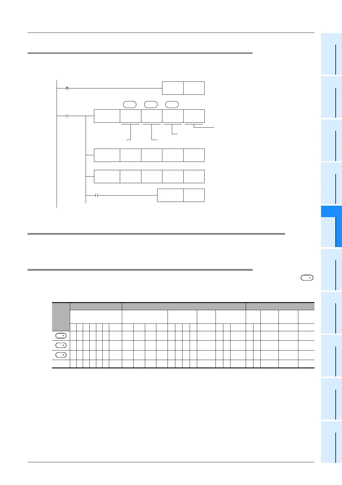
9.7.3 Program example of "second parameter specification code"
→ For second parameter specification code, refer to Section 9.9.
In the program example shown below, data is written from the PLC to the parameters (frequency: 201, time:
1201, motor rotation direction: 2201) in the A500 inverter.
9.8 Inverter Parameter Batch Writing (PLC→Inverter) [FNC274 / IVBWR]
This instruction writes values from the PLC to parameters in an inverter all at once.
The IVBWR instruction is supported only in FX
3U and FX3UC PLCs.
9.8.1 Function and operation
When a parameter number in an inverter is specified in the IVBWR (FNC274) instruction, the values of
and later are written to the specified items in the inverter all at once.
1. Applicable devices
Oper-
and
Type
Bit Devices Word Devices Others
System/User Digit Specification System/User
Special
Unit
Index
Con-
stant
Real
Number
Charac-
ter String
Pointer
XYMTCSD
.b KnX KnY KnM KnS T C D R
U\G
VZModifyKH E "
"P
n
M0
FNC273
IVWR
K6 K2201 H1
S
1
S
2
S
3
Drive
contact
Value written to inverter
Inverter parameter number (decimal)
FNC273
IVWR
K6 K201 H14
FNC273
IVWR
K6 K1201 H100
M8029
RST M0
Execution complete flag
Motor rotation direction: Forward
Frequency: 20Hz
Time: 1:00
The unit is specified by Pr. 200.
X001
SET M0
Write
command
Inverter station
number: 0 to 31
K1
n
Communication channel K1:ch1
K1
K1
S
3
S
1
S
2
S
3
 Loading...


