E-96
FX Series PLC User's Manual - Data Communication Edition
Inverter Communication
9 Creating Programs (for FX3G, FX3U and FX3UC PLCs)
9.8 Inverter Parameter Batch Writing (PLC
→
Inverter) [FNC274 / IVBWR]
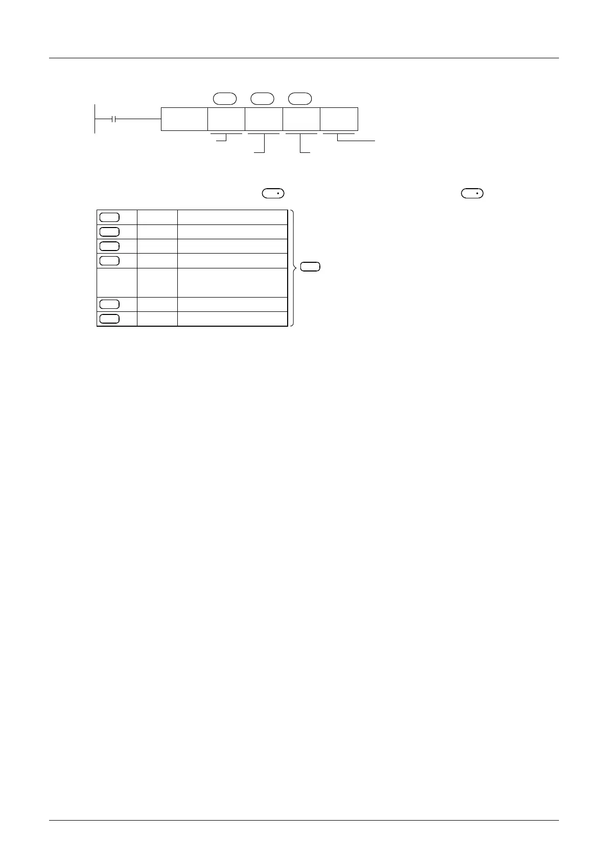
2. Program example
The following table shows values (two word devices/point) in a specified table which are written to a number
of consecutive parameters specified in starting from a word device specified in .
M0
FNC274
IVBWR
K6 K8 D200
S
1
S
2
S
3
Command
contact
Inverter station number: 0 to 31
Head device of parameter
table written to inverter
Number of parameters to be written
(decimal)
K1
n
Communication channel K1: ch1
K2: ch2
S
2
S
3
×
2 = Number of occupied word devices
S
2
S
3
+1
S
3
+2
S
3
+3
S
3
:
:
+14
S
3
+15
S
3
D200
D201
D202
D203
:
:
D214
D215
Parameter No. 1
Value 1 written to parameter
Parameter No. 2
Value 2 written to parameter
Parameter No. 8
Value 8 written to parameter
:
:
 Loading...


