M800S/M80/E80 Series Connection and Setup Manual
4 General Specifications
139
IB-1501269-J
(2) Measures against back EMF
Provide a contact protection circuit for an extended contact life, noise prevention at contact close, and
reduction of the carbides and nitric acids formed by an arc discharge.
An incorrect circuit involves a high risk of contact welding.
With the contact protection circuit, the recovery time may be delayed.
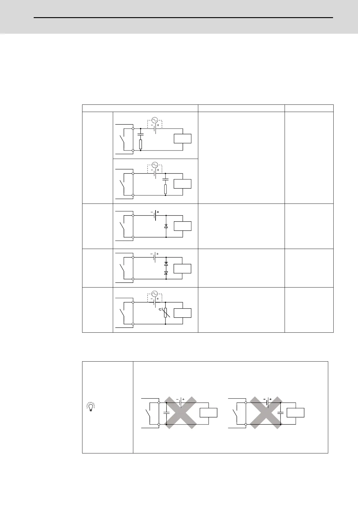
The following table shows typical examples of the contact protection circuit.
(Note 1) On AC power supply, the impedance of the CR needs to be sufficiently higher than that of the
load (for preventing errors due to the leakage current of the CR).
Circuit example Element selection criteria Remarks
Capacitor +
resistance
method (CR
method)
Estimate the constants of a capacitor
and resistance with the following as a
guide. Some differences, however, may
arise from a variation in the nature and
characteristics of the load.
・Capacitor: 0.5 to 1 (μF) for a load
current of 1A
・Resistance: 0.5 to 1 (Ω) for a power
supply voltage of 1V
Use a capacitor whose withstand
voltage is higher than the rated voltage.
In an AC circuit, use a capacitor with no
polarity.
When a relay or
solenoid is used as
the load, the recovery
time is delayed.
A capacitor has the
effect of reducing a
discharge at contact
OFF, while a
resistance has the
effect of limiting a
current at contact ON.
Diode
method
Use a diode that satisfies the following
conditions:
・A reverse breakdown voltage is more
than ten times as high as the circuit
voltage.
・A forward current is more than twice as
high as the load current.
The recovery time is
delayed than the CR
method.
Diode + zener
diode method
Use a zener diode whose zener voltage
is higher than the power supply voltage.
This method is
suitable for the case
where the diode
method results in a
substantial delay in
the recovery time.
Varistor
method
Select a varistor whose cut-off voltage
(Vc) satisfies the following conditions:
・Vc > power supply voltage×1.5 (V)
・Vc > power supply voltage×1.5 (V)× √
2 (on AC power supply)
Note that selecting an element of a too
high Vc leads to a weaker effect.
The recovery time is a
little delayed.
・Avoid using contact protection circuits like the following. Although highly effective in
reducing the arc at current cutoff, a charge current flows into the capacitor when the contact
turns on or off, which leads to the risk of contact welding. A DC inductive load, generally
considered to be more difficult to open and close than a resistive load, can achieve the same
performance of a resistive load in an appropriate configuration of the protection circuit.
Install the protection circuit near the load or contact (module). A long distance between them
may inhibit the effect of the protection circuit. As a guide, install it at a distance of no more
than 50cm.
(Note 1)
Capacitor
Resistor
Inductive
load
Capacitor
Resistor
Inductive
load
Zener Diode
Diode
Inductive
load
Varistor
Inductive
load
POINT
Capacitor
Capacitor
Inductive
load
Inductive
load

 Loading...


